

Question: Create a logic diagram for controlling (switching) a predefined segment of a 7-segment indicator using logic elements of the predefined type in the diagram (and
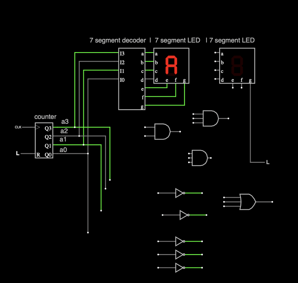
Create a logic diagram for controlling (switching) a predefined segment of a 7-segment indicator using logic elements of the predefined type in the diagram (and the appropriate / required normal shape). falstad.com
Segment: E Logic gates you can use in falstad: AND, OR, INV Normal shape: Minimal disjunctive normal form NEGATIVE logic
The difference is due to the fact that there are at least two variants of LED matrices / common indicators (common cathode, common anode). Falstad only offers the first option, so an inverter must be inserted into the test output of the negative logic circuit for the indicator to work properly.
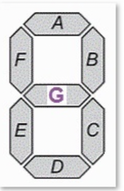 my segment is E.
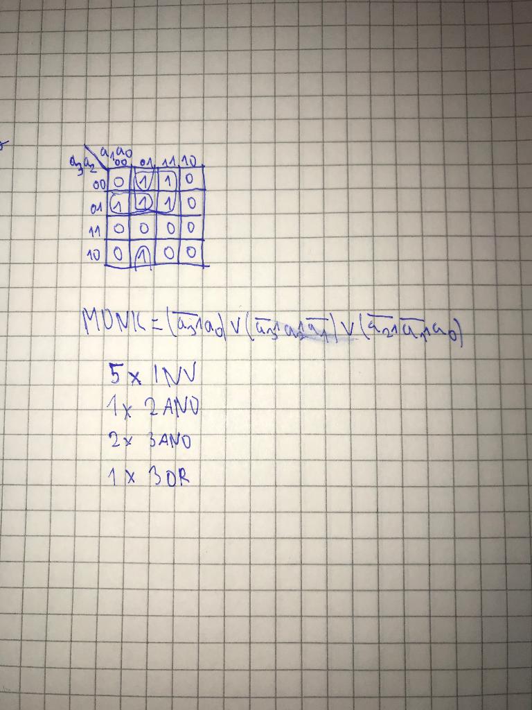
A B G E D aaa ,, , .10 000 M10 on 1000 111001010 10/0alolo MONK = Cartad varan fly larianaof 5% IN 11 2 ANO 2. BANO 1 X BOR 7 segment decoder | 7 segment LED 17 segment LED 13 aa a 12 b b b A 11 C C IO d d e d f g T e T e f counter a3 CLK Q3 Q2 Q1 R QO a2 a1 D L :D. 9
Step by Step Solution
There are 3 Steps involved in it

Get step-by-step solutions from verified subject matter experts