

Question: Create an assembly drawing showing the fully assembled vice ( see below for example ) . Use the parts created in the first step along
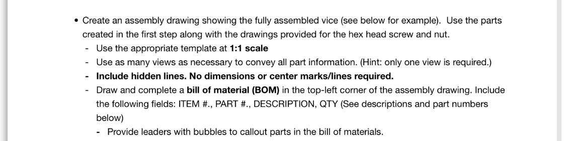
Create an assembly drawing showing the fully assembled vice see below for example Use the parts created in the first step along with the drawings provided for the hex head screw and nut.
Use the appropriate template at : scale
Use as many views as necessary to convey all part information. Hint: only one view is required.
Include hidden lines. No dimensions or center markslines required.
Draw and complete a bill of material BOM in the topleft corner of the assembly drawing. Include the following fields: ITEM # PART # DESCRIPTION, QTY See descriptions and part numbers below
Provide leaders with bubbles to callout parts in the bill of materials.
Step by Step Solution
There are 3 Steps involved in it
1 Expert Approved Answer
Step: 1 Unlock

Question Has Been Solved by an Expert!
Get step-by-step solutions from verified subject matter experts
Step: 2 Unlock
Step: 3 Unlock