

Question: ***** create test bench for the function using verilog xilinx and please show the waveform *******. (PLEASE ONLY ANSWER IF YOU UNDERSTAND HOW TO USE
***** create test bench for the function using verilog xilinx and please show the waveform *******. (PLEASE ONLY ANSWER IF YOU UNDERSTAND HOW TO USE XILINX.
In simple words, majority function reflects the status of the majority of the input lines. This function gives output 1 if most of its input lines (more than half the count of input lines) are 1; otherwise 0. For the given scenario with 3 input lines (x, y, z), the truth table for the majority function (or in a block: gate) will look as follows.
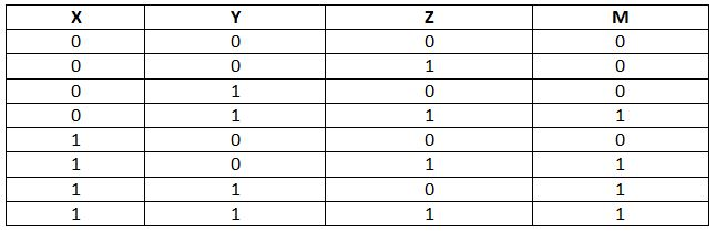
Clearly, for the row (0, 1, 1) or (1, 1, 1) the output is 1 as there are two 1s amongst 3 input lines. However, for the row (0, 0, 1) or (0, 0, 0), the output remains 0 as the count of 1s are less than 0s.
The code for this problem is written in Verilog in the following however, the requirements of ROM to this code is not clearly mentioned in the question, thus this problem is solved using registers. For ROM usage, kindly post this question with more detail.
CODE:
module function( M );
output reg M;
reg X; reg Y; reg Z;
always
begin
#5 Z
end
always
begin
#10 Y
end
always
begin
#20 X
end
always @ (X or Y or Z)
begin
if ( (Y && Z) || (X && Z) || (X && Y) )
M = 1'b1;
else
M = 1'b 0;
end
initial
begin
$monitor("X:%b Y:%b Z:%b Majority:%b ", X, Y, Z, M);
X
end
endmodule
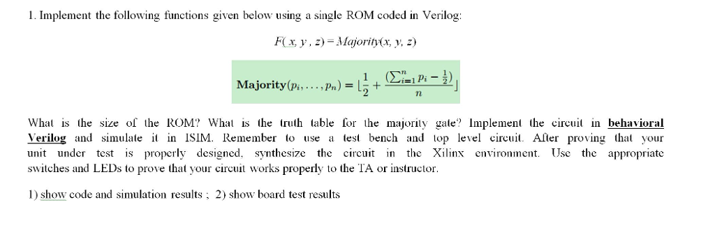
1. Implement the following functions given below using a single ROM coded in Verilog: F(x, y, z) Majority(x, y, z) Majority(Pi, . . . , pn)=L2 +e-in 2- What is the size of the ROM? Wha is the truth table for the majority gate Implement the circuit in behavioral Verilog and simulate in ISIM. Remember o use a test bench and top level circi Afler proving that your unit under test s properly designed. synthesize the circuit in the Xilinx environment. Use the appropriate switches and LEDs to prove that your circuit works properly to the TA or instructor. 1) show code and simulation results: 2 show board test results 1. Implement the following functions given below using a single ROM coded in Verilog: F(x, y, z) Majority(x, y, z) Majority(Pi, . . . , pn)=L2 +e-in 2- What is the size of the ROM? Wha is the truth table for the majority gate Implement the circuit in behavioral Verilog and simulate in ISIM. Remember o use a test bench and top level circi Afler proving that your unit under test s properly designed. synthesize the circuit in the Xilinx environment. Use the appropriate switches and LEDs to prove that your circuit works properly to the TA or instructor. 1) show code and simulation results: 2 show board test results
Step by Step Solution
There are 3 Steps involved in it

Get step-by-step solutions from verified subject matter experts