

Question: Create the packet switching network which has 3 hubs and 12 peripheral nodes similar to the network topology shown in Figure 1. You are required
Create the packet switching network which has 3 hubs and 12 peripheral nodes similar to the network topology shown in Figure 1. You are required to define the packet format and connections links. Then by using OPNET kernel functions, you will collect statistics. Figure1.Network topology with 3 subnetworks Your end product will be a simulation that will demonstrate transmission of the packets over the packet switching network.....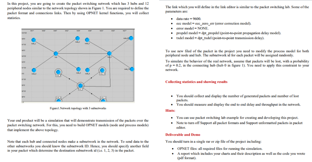
In this project, you are going to create the packet switching network which has 3 hubs and 12 peripheral nodes similar to the network topology shown in Figure1. You are required to define the packet format and connections links. Then by using OPNET kernel functions, you will collect statisticS The link which you will define in the link editor is similar to the packet switching lab. Some of the parameters are: data rate = 9600. ccc model = ccc zero err (error correction model). . error model-NONE * propdel model -dpt_propdel (point-to-point propagation delay model) * txdel model- dpt txdel (point-to-point transmission delay To use new filed of the packet in the project you need to modify the process model for both peripheral node and hub. The subnetwork id for each packet will be assigned randomly To simulate the behavior of the real network, assume that packets will be lost, with a probability of p - 0.2, in the connecting hub (hub 0 in figure 1). You need to apply this constraint to your network Collecting statistics and showing results .You should collect and display the number of generated packets and number of lost packets. You should measure and display the end to end delay and throughput in the network. Figurel.Network topology with 3 subnctworks Hints: You can use packet switching lab example for creating and developing this project Note to turn off Support all packet formats and Support unformatted packets in packet Your end product will be a simulation that will demonstrate transmission of the packets over the packet switching network. For this, you need to build OPNET models (node and process models) that implement the above topology editor Deliverable and Demo Note that each hub and connected nodes make a subnetwork in the network, To send data to the other subnetworks you should know the subnetwork ID. Hence, you should specify another field in your packet which determine the destination subnetwork id (ie. 1, 2, 3) in the packet. You should turn in a single rar or zip file of the project including: OPNET files: all required files for running the simulation. .A report which includes your charts and their description as well as the code you wrote (pdf format). In this project, you are going to create the packet switching network which has 3 hubs and 12 peripheral nodes similar to the network topology shown in Figure1. You are required to define the packet format and connections links. Then by using OPNET kernel functions, you will collect statisticS The link which you will define in the link editor is similar to the packet switching lab. Some of the parameters are: data rate = 9600. ccc model = ccc zero err (error correction model). . error model-NONE * propdel model -dpt_propdel (point-to-point propagation delay model) * txdel model- dpt txdel (point-to-point transmission delay To use new filed of the packet in the project you need to modify the process model for both peripheral node and hub. The subnetwork id for each packet will be assigned randomly To simulate the behavior of the real network, assume that packets will be lost, with a probability of p - 0.2, in the connecting hub (hub 0 in figure 1). You need to apply this constraint to your network Collecting statistics and showing results .You should collect and display the number of generated packets and number of lost packets. You should measure and display the end to end delay and throughput in the network. Figurel.Network topology with 3 subnctworks Hints: You can use packet switching lab example for creating and developing this project Note to turn off Support all packet formats and Support unformatted packets in packet Your end product will be a simulation that will demonstrate transmission of the packets over the packet switching network. For this, you need to build OPNET models (node and process models) that implement the above topology editor Deliverable and Demo Note that each hub and connected nodes make a subnetwork in the network, To send data to the other subnetworks you should know the subnetwork ID. Hence, you should specify another field in your packet which determine the destination subnetwork id (ie. 1, 2, 3) in the packet. You should turn in a single rar or zip file of the project including: OPNET files: all required files for running the simulation. .A report which includes your charts and their description as well as the code you wrote (pdf format)
Step by Step Solution
There are 3 Steps involved in it

Get step-by-step solutions from verified subject matter experts