

Question: CS413 Lab 4 ARM GPIO LEDs Purpose: Use ARM assembly on the Raspberry Pi and the provided circuit interfaced via the General Purpose Input/Output (GPIO)

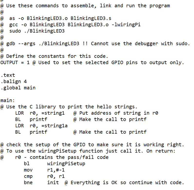
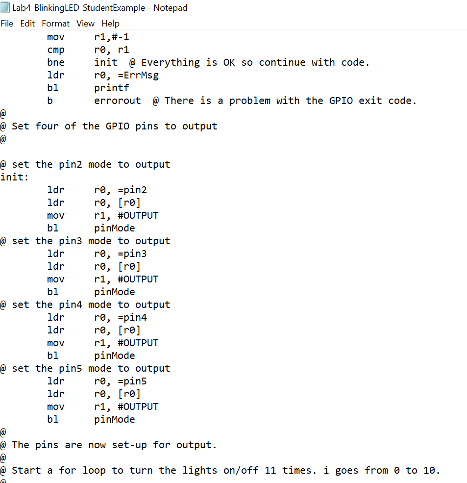
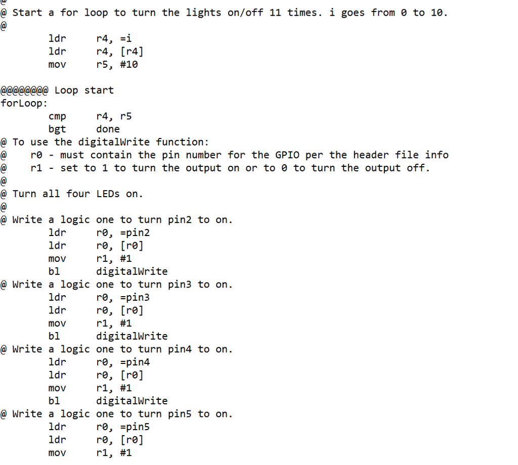

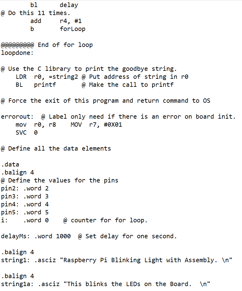
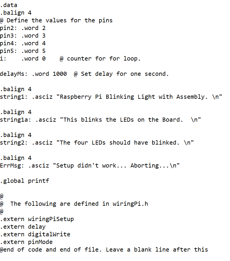
CS413 Lab 4 ARM GPIO LEDs Purpose: Use ARM assembly on the Raspberry Pi and the provided circuit interfaced via the General Purpose Input/Output (GPIO) control the LEDs in a specific pattern. The attached text file contains ARM assembly code that controls the LEDs on the Raspberry Pi. Use the example code in this file to implement your program BlinkingLED_Stude ntExample.s Write an ARM program that will use the four LEDs on the circuit board to count in binary from 0 to F. The program will: 1. Print a welcome message and what the program is about to perform 2. Turn all the LEDs on. 3. Turn all the LEDs off. 4. Start the binary count from 0 to F. Perform this count a total of three times 5. Turn all the LEDs off. 6. Turn all the LEDs on 7. Turn all the LEDs off. 8. Print an exit message and end the program. CS413 Lab 4 ARM GPIO LEDs Purpose: Use ARM assembly on the Raspberry Pi and the provided circuit interfaced via the General Purpose Input/Output (GPIO) control the LEDs in a specific pattern. The attached text file contains ARM assembly code that controls the LEDs on the Raspberry Pi. Use the example code in this file to implement your program BlinkingLED_Stude ntExample.s Write an ARM program that will use the four LEDs on the circuit board to count in binary from 0 to F. The program will: 1. Print a welcome message and what the program is about to perform 2. Turn all the LEDs on. 3. Turn all the LEDs off. 4. Start the binary count from 0 to F. Perform this count a total of three times 5. Turn all the LEDs off. 6. Turn all the LEDs on 7. Turn all the LEDs off. 8. Print an exit message and end the program
Step by Step Solution
There are 3 Steps involved in it

Get step-by-step solutions from verified subject matter experts