

Question: Dear, the first picture, the question, the second, the third, and the fourth, the answer that is required of you is only to present the
Dear, the first picture, the question, the second, the third, and the fourth, the answer that is required of you is only to present the solution to the question, with an explanation of all the steps of the solution
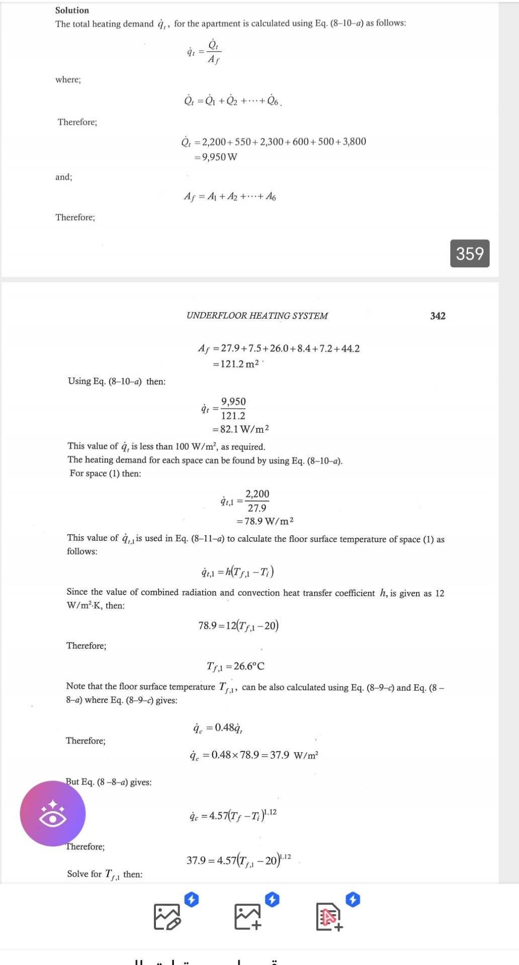
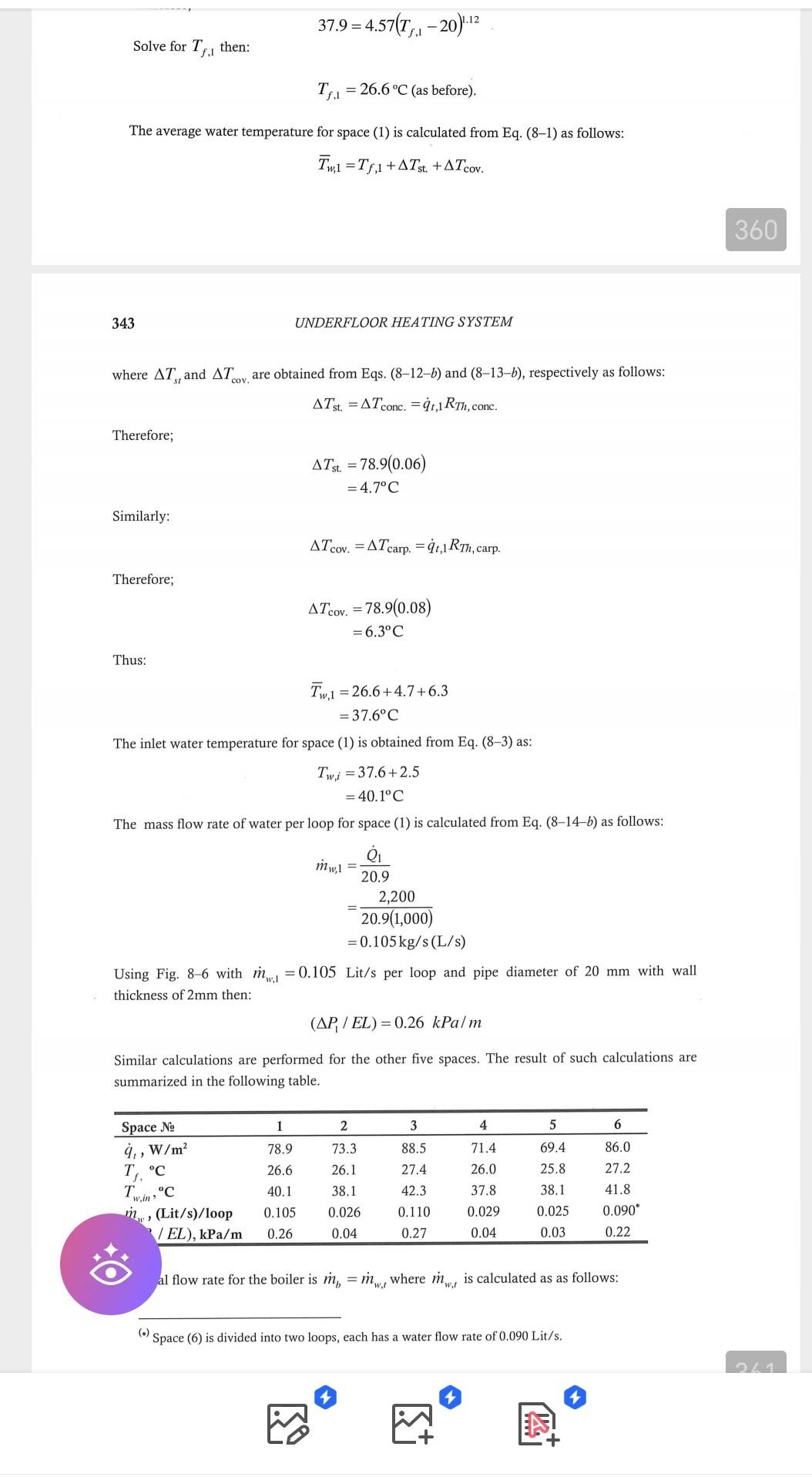
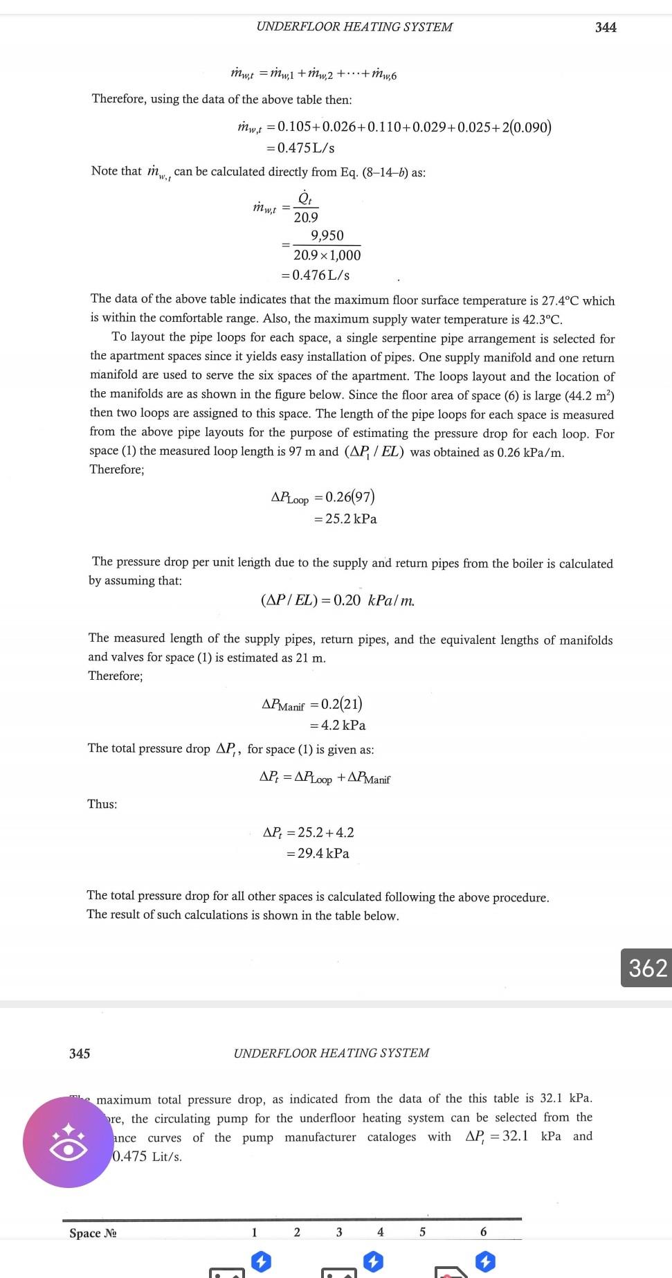
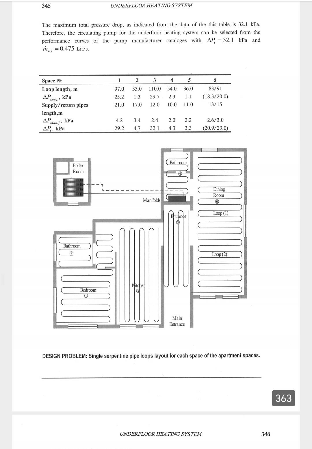
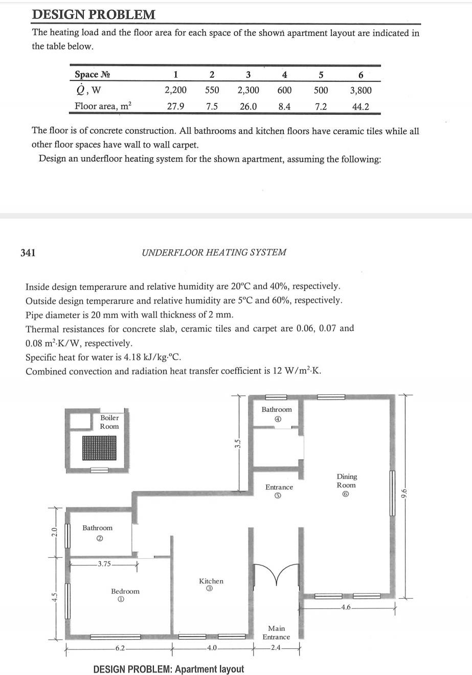
The heating load and the floor area for each space of the shown apartment layout are indicated in the table below. The floor is of concrete construction. All bathrooms and kitchen floors have ceramic tiles while all other floor spaces have wall to wall carpet. Design an underfloor heating system for the shown apartment, assuming the following: 341 UNDERFLOOR HEATING SYSTEM Inside design temperarure and relative humidity are \\( 20^{\\circ} \\mathrm{C} \\) and \40, respectively. Outside design temperarure and relative humidity are \\( 5^{\\circ} \\mathrm{C} \\) and \60, respectively. Pipe diameter is \\( 20 \\mathrm{~mm} \\) with wall thickness of \\( 2 \\mathrm{~mm} \\). Thermal resistances for concrete slab, ceramic tiles and carpet are 0.06, 0.07 and \\( 0.08 \\mathrm{~m}^{2} \\cdot \\mathrm{K} / \\mathrm{W} \\), respectively. Specific heat for water is \\( 4.18 \\mathrm{~kJ} / \\mathrm{kg} \\cdot{ }^{\\circ} \\mathrm{C} \\). Combined convection and radiation heat transfer coefficient is \\( 12 \\mathrm{~W} / \\mathrm{m}^{2} \\cdot \\mathrm{K} \\). UESIGN PKUBLEI: Apartment Iayout Solution The total heating demand \\( \\dot{q}_{t} \\), for the apartment is calculated using Eq. (8-10-a) as follows: \\[ \\dot{q}_{t}=\\frac{\\dot{Q}_{t}}{A_{f}} \\] where; \\[ \\dot{Q}_{t}=\\dot{Q}_{1}+\\dot{Q}_{2}+\\cdots+\\dot{Q}_{6} \\] Therefore; \\[ \\begin{aligned} \\dot{Q}_{t} & =2,200+550+2,300+600+500+3,800 \\\\ & =9,950 \\mathrm{~W} \\end{aligned} \\] and; \\[ A_{f}=A_{1}+A_{2}+\\cdots+A_{6} \\] Therefore; UNDERFLOOR HEATING SYSTEM 342 \\[ \\begin{aligned} A_{f} & =27.9+7.5+26.0+8.4+7.2+44.2 \\\\ & =121.2 \\mathrm{~m}^{2} \\end{aligned} \\] Using Eq. (8-10-a) then: \\[ \\begin{aligned} \\dot{q}_{t} & =\\frac{9,950}{121.2} \\\\ & =82 \\cdot 1 \\mathrm{~W} / \\mathrm{m}^{2} \\end{aligned} \\] This value of \\( \\dot{q}_{t} \\), is less than \\( 100 \\mathrm{~W} / \\mathrm{m}^{2} \\), as required. The heating demand for each space can be found by using Eq. (8-10-a). For space (1) then: \\[ \\begin{aligned} \\dot{q}_{t, 1} & =\\frac{2,200}{27.9} \\\\ & =78.9 \\mathrm{~W} / \\mathrm{m}^{2} \\end{aligned} \\] This value of \\( \\dot{q}_{t, 1} \\) is used in Eq. (8-11-a) to calculate the floor surface temperature of space (1) as follows: \\[ \\dot{q}_{t, 1}=h\\left(T_{f, 1}-T_{i}\ ight) \\] Since the value of combined radiation and convection heat transfer coefficient \\( h \\), is given as 12 \\( \\mathrm{W} / \\mathrm{m}^{2} \\cdot \\mathrm{K} \\), then: \\[ 78.9=12\\left(T_{f, 1}-20\ ight) \\] Therefore; \\[ T_{f, 1}=26.6^{\\circ} \\mathrm{C} \\] Note that the floor surface temperature \\( T_{f, 1} \\), can be also calculated using Eq. (8-9-c) and Eq. (8\\( 8-a \\) ) where Eq. (8-9-c) gives: Therefore; \\[ \\dot{q}_{c}=0.48 \\dot{q}_{t} \\] \\[ \\dot{q}_{c}=0.48 \\times 78.9=37.9 \\mathrm{~W} / \\mathrm{m}^{2} \\] But Eq. (8-8-a) gives: \\[ \\dot{q}_{c}=4.57\\left(T_{f}-T_{i}\ ight)^{1.12} \\] Therefore; Solve for \\( T_{f, 1} \\) then: \\[ 37.9=4.57\\left(T_{f, 1}-20\ ight)^{1.12} \\] \\[ 37.9=4.57\\left(T_{f, 1}-20\ ight)^{1.12} \\] Solve for \\( T_{f, 1} \\) then: \\[ T_{f, 1}=26.6^{\\circ} \\mathrm{C} \\text { (as before). } \\] The average water temperature for space (1) is calculated from Eq. (8-1) as follows: \\[ \\bar{T}_{w, 1}=T_{f, 1}+\\Delta T_{\\text {st. }}+\\Delta T_{\\text {cov. }} \\] 343 UNDERFLOOR HEATING SYSTEM where \\( \\Delta T_{s t} \\) and \\( \\Delta T_{\\text {cov, }} \\) are obtained from Eqs. (8-12-b) and (8-13-b), respectively as follows: \\[ \\Delta T_{\\text {st. }}=\\Delta T_{\\text {conc. }}=\\dot{q}_{t, 1} R_{T h, \\text { conc. }} \\] Therefore; \\[ \\begin{aligned} \\Delta T_{\\text {st. }} & =78.9(0.06) \\\\ & =4.7^{\\circ} \\mathrm{C} \\end{aligned} \\] Similarly: \\[ \\Delta T_{\\text {cov. }}=\\Delta T_{\\text {carp. }}=\\dot{q}_{t, 1} R_{T h, \\text { carp. }} \\] Therefore; \\[ \\begin{aligned} \\Delta T_{\\text {cov. }} & =78.9(0.08) \\\\ & =6.3^{\\circ} \\mathrm{C} \\end{aligned} \\] Thus: \\[ \\begin{aligned} \\bar{T}_{w, 1} & =26.6+4.7+6.3 \\\\ & =37.6^{\\circ} \\mathrm{C} \\end{aligned} \\] The inlet water temperature for space (1) is obtained from Eq. (8-3) as: \\[ \\begin{aligned} T_{w, i} & =37.6+2.5 \\\\ & =40.1^{\\circ} \\mathrm{C} \\end{aligned} \\] The mass flow rate of water per loop for space (1) is calculated from Eq. (8-14-b) as follows: \\[ \\begin{aligned} \\dot{m}_{w, 1} & =\\frac{\\dot{Q}_{1}}{20.9} \\\\ & =\\frac{2,200}{20.9(1,000)} \\\\ & =0.105 \\mathrm{~kg} / \\mathrm{s}(\\mathrm{L} / \\mathrm{s}) \\end{aligned} \\] Using Fig. 8-6 with \\( \\dot{m}_{w, 1}=0.105 \\mathrm{Lit} / \\mathrm{s} \\) per loop and pipe diameter of \\( 20 \\mathrm{~mm} \\) with wall thickness of \\( 2 \\mathrm{~mm} \\) then: \\[ \\left(\\Delta P_{1} / E L\ ight)=0.26 \\mathrm{kPa} / \\mathrm{m} \\] Similar calculations are performed for the other five spaces. The result of such calculations are summarized in the following table. al flow rate for the boiler is \\( \\dot{m}_{b}=\\dot{m}_{w, t} \\) where \\( \\dot{m}_{w, t} \\) is calculated as as follows: \\( { }^{()} \\) Space (6) is divided into two loops, each has a water flow rate of \\( 0.090 \\mathrm{Lit} / \\mathrm{s} \\). UNDERFLOOR HEATING SYSTEM 344 \\[ \\dot{m}_{w, t}=\\dot{m}_{w, 1}+\\dot{m}_{w, 2}+\\cdots+\\dot{m}_{w, 6} \\] Therefore, using the data of the above table then: \\[ \\begin{aligned} \\dot{m}_{w, t} & =0.105+0.026+0.110+0.029+0.025+2(0.090) \\\\ & =0.475 \\mathrm{~L} / \\mathrm{s} \\end{aligned} \\] Note that \\( \\dot{m}_{w, t} \\) can be calculated directly from Eq. (8-14-b) as: \\[ \\begin{aligned} \\dot{m}_{w, t} & =\\frac{\\dot{Q}_{t}}{20.9} \\\\ & =\\frac{9,950}{20.9 \\times 1,000} \\\\ & =0.476 \\mathrm{~L} / \\mathrm{s} \\end{aligned} \\] The data of the above table indicates that the maximum floor surface temperature is \\( 27.4^{\\circ} \\mathrm{C} \\) which is within the comfortable range. Also, the maximum supply water temperature is \\( 42.3^{\\circ} \\mathrm{C} \\). To layout the pipe loops for each space, a single serpentine pipe arrangement is selected for the apartment spaces since it yields easy installation of pipes. One supply manifold and one return manifold are used to serve the six spaces of the apartment. The loops layout and the location of the manifolds are as shown in the figure below. Since the floor area of space (6) is large \\( \\left(44.2 \\mathrm{~m}^{2}\ ight) \\) then two loops are assigned to this space. The length of the pipe loops for each space is measured from the above pipe layouts for the purpose of estimating the pressure drop for each loop. For space (1) the measured loop length is \\( 97 \\mathrm{~m} \\) and \\( \\left(\\Delta P_{1} / E L\ ight) \\) was obtained as \\( 0.26 \\mathrm{kPa} / \\mathrm{m} \\). Therefore; \\[ \\begin{aligned} \\Delta P_{\\text {Loop }} & =0.26(97) \\\\ & =25.2 \\mathrm{kPa} \\end{aligned} \\] The pressure drop per unit length due to the supply and return pipes from the boiler is calculated by assuming that: \\[ (\\triangle P / E L)=0.20 \\mathrm{kPa} / \\mathrm{m} \\] The measured length of the supply pipes, return pipes, and the equivalent lengths of manifolds and valves for space (1) is estimated as \\( 21 \\mathrm{~m} \\). Therefore; \\[ \\begin{aligned} \\Delta P_{\\text {Manif }} & =0.2(21) \\\\ & =4.2 \\mathrm{kPa} \\end{aligned} \\] The total pressure drop \\( \\Delta P_{t} \\), for space (1) is given as: \\[ \\Delta P_{t}=\\Delta P_{\\text {Loop }}+\\Delta P_{\\text {Manif }} \\] Thus: \\[ \\begin{aligned} \\Delta P_{t} & =25.2+4.2 \\\\ & =29.4 \\mathrm{kPa} \\end{aligned} \\] The total pressure drop for all other spaces is calculated following the above procedure. The result of such calculations is shown in the table below. 345 UNDERFLOOR HEATING SYSTEM maximum total pressure drop, as indicated from the data of the this table is \\( 32.1 \\mathrm{kPa} \\). re, the circulating pump for the underfloor heating system can be selected from the ance curves of the pump manufacturer cataloges with \\( \\Delta P_{t}=32.1 \\mathrm{kPa} \\) and \\( 0.475 \\mathrm{Lit} / \\mathrm{s} \\). The maximum total pressure drop, as indicated from the data of the this table is \\( 32.1 \\mathrm{kPa} \\). Therefore, the circulating pump for the underfloor heating system can be selected from the performance curves of the pump manufacturer cataloges with \\( \\Delta P_{t}=32.1 \\mathrm{kPa} \\) and \\( \\dot{m}_{w, t}=0.475 \\mathrm{Lit} / \\mathrm{s} \\). DESIGN PROBLEM: Single serpentine pipe loops layout for each space of the apartment spaces
Step by Step Solution
There are 3 Steps involved in it

Get step-by-step solutions from verified subject matter experts