

Question: Description In this assignment you will convert a high-level state machine into a datapath and integrate it with a corresponding controller. You are given a
 Description In this assignment you will convert a high-level state machine into a datapath and integrate it with a corresponding controller. You are given a state diagram of a calculator display controller, which must be converted into a controller circuit. This controller will be integrated into the datapath of an 8-bit calculator and used to control it. Multiple other components must be implemented and used in the datapath to make the 8-bit calculator work. The calculator has one 8-bit input, 5 buttons (equal, add, subtract, multiply and divide) and two 4-bit outputs for two hex displays (see figure 1). The user can interact with the calculator by changing the input and pressing the buttons. Figure 1: Final Project Part 2 Calculator Interface The calculator is supposed to take in two numbers and perform the selected operation with those two numbers. The result will just consist of whole numbers, the fractions are truncated/ignored. Also, negative numbers will not be considered. To use the calculator, the user will follow these steps: 1. Set the value of the first number on the 8-bit input. Changing this input value should not be visible on the display. 2. Once the user has set the correct value of the first number, an operator must be pressed. This stores the first number, the selected operator and shows the first number on the display in hexadecimal representation. 3. Optionally, the user can change the value of the first number (again, changing the input should not be visible on the output) and/or change the operator by pressing a different operator button than before. Pressing any of the operator buttons updates the stored value of the first number, updates the stored operator and shows the updated first number on the display. 4. After storing the first number by selecting an operator, the user can now input the value of the second number using the 8-bit input. Once the input value is set, the user can press the equal button to see the correct result of the calculation on the display in hexadecimal representation. 5. Optionally, the user can change the value of the second number by changing the 8-bit input and pressing equal again. This updates the result on the display with the changed second number. 6. Now the calculator is ready to do the next calculation: Setting the input value to the first number and pressing an operator starts a new calculation (see step 1 and 2). The result of the previous calculation does not have an effect on the following (e.g. must not be used for the following calculation in any way). Tasks Before working on this project, download the provided template for this project part from Blackboard. You must use this template in order to receive points for this project. For this project, you are allowed to use any built-in circuit elements of Logisim (e.g. multiplexers, registers, adders, etc.). In the template, you will see two subcircuits created for you: Controller and Datapath. The following sections each describe what you are supposed to create within those two subcircuits. You are not allowed to change anything in the circuit Calculator Interface. In circuit 8-Bit Calculator, you are only allowed to add wires and use splitters. You are allowed to create as many subcircuits as you want and use them within Datapath. Controller Similar to Final Project Part 1, you are supposed to create a controller circuit from a finite state machine (FSM). Figure 2 shows the state diagram of the calculator display controller. Use the same process as in Final Project Part 1 to turn this state diagram into a controller circuit in Logisim. This circuit goes into the Controller subcircuit of the template. Description of the state diagram: Figure 2: Calculator display state diagram. Inputs of the diagram are: Op: Pressing any of the operator buttons ( + - * / ) Eq: Pressing the equal button ( = ) Outputs of the diagram are: y: Output current encoded state State First number displayed: In this state the selected operator and first number is stored, and the first number is displayed on the output. Pressing no button will not change the state. Pressing an operator button repeatedly updates the stored operator, stored first number and the display output. State Result displayed: In this state the second number is stored and the result of the calculation is displayed. Pressing no button will not change the state. Pressing equal repeatedly updates the stored second number and the display output. Encode the states as follows: First number displayed = 0 and Result displayed = 1. Do the following steps: 1. Create the truth table for this state diagram. (Must not be submitted) 2. Derive the Boolean equations from the truth table for all outputs. (Must not be submitted) 3. Create the controller circuit from the Boolean equations. This circuit goes into the Controller subcircuit of the provided template. Datapath To make the calculator work, you have to create datapath components for the Datapath subcircuit: 1. Create an ALU that can calculate the result for the basic arithmetic operations (addition, subtraction, multiplication, division) for two 8-bit values. The ALU should output the needed result depending on the selected operation. 2. Use 3 registers to store the first number, selected operator and second number. Remember that registers store the values on the input during a rising edge (default setting in Logisim). You dont necessarily need a clock to generate a rising edge: E.g. pressing a button also generates a rising edge. 3. Use a multiplexer to select the correct display value based on the output of the calculator display controller circuit.
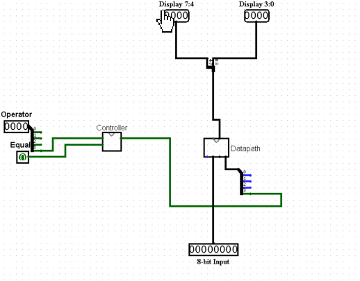
I need to know how to connect the circuit labeled 8 bit calculator.
Display 7:4 Display 3:0 Operator Equa Datapath Th 8-bit Input Display 7:4 Display 3:0 Operator Equa Datapath Th 8-bit Input
Step by Step Solution
There are 3 Steps involved in it

Get step-by-step solutions from verified subject matter experts