

Question: Description The assignment is designed to test your knowledge about Behavioral - Level Design ( Program to Circuit ) including High - Level State Machines
Description
The assignment is designed to test your knowledge about BehavioralLevel Design Program to Circuit including HighLevel State Machines HLSMs and the use of Hardware Descriptive Language HDL
Questions
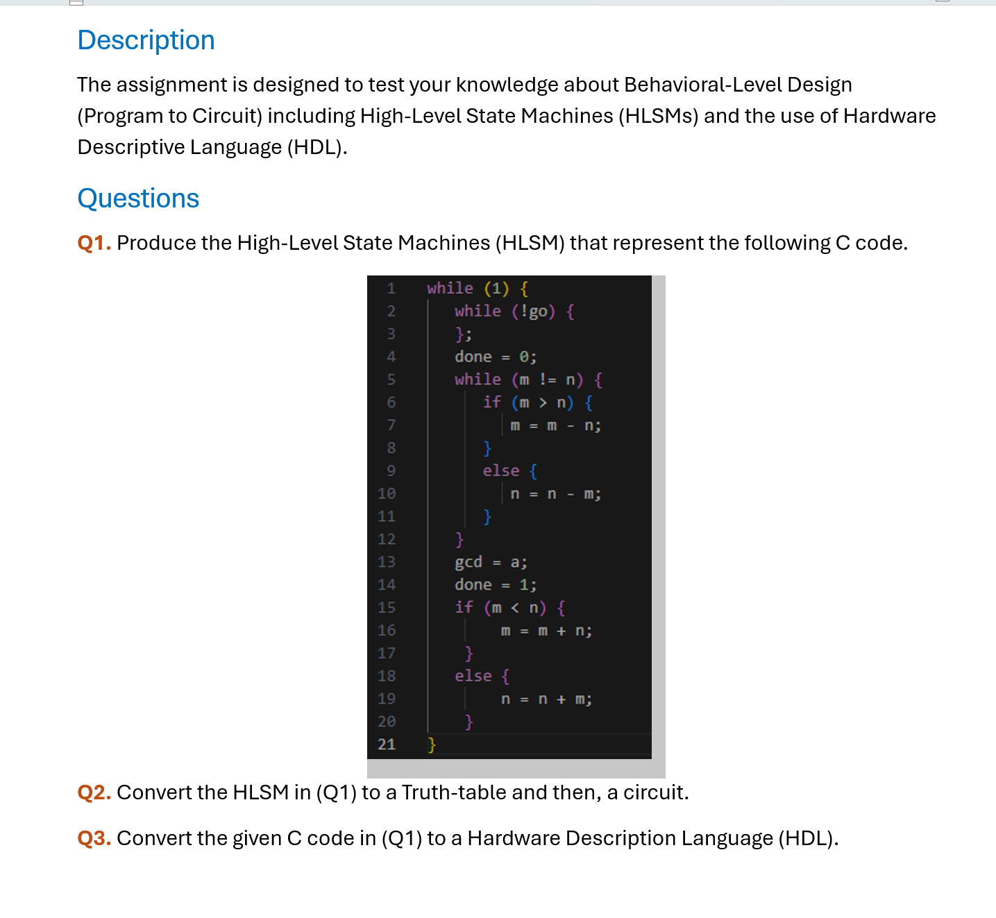
Q Produce the HighLevel State Machines HLSM that represent the following C code.
Code:
while
while go
;
done ;
while m n
if m n
mmn;
else
n n m;
gcd a;
done ;
if m n
m m n;
else
n n m;
Q Convert the HLSM in Q to a Truthtable and then, a circuit.
Q Convert the given C code in Q to a Hardware Description Language HDL
Hint: If you translated the C program very well, you should have states in total.
With states, you would need to encode each state with bits.
Datapath component : you would need a comparator for mn mn so all the three outputs from the comparator should go to the controller as inputs. This increases the number of inputs for your truth table to bits bits for state encoding, bit for go input, and bits from comparator
Datapath components : you need two subtractors one for n nm and one for mmn and two adders one for nnm one for mmn a multiplexer and a load register for done n and m outputs each, and just a register for gcd output. The inputs to the multiplexers and registers would come from the combinational circuit part of the controller.
Therefore, bits for the state encoding bit for the input gobits for the comparator, making a total of bits is needed to construct your truthtable.
I know this cannot be done with hand. I suggest you leave out the truthtable part and just come up with a circuit diagram showing the Datapath component and the inputoutput of the state registers. You can just represent the combinational circuit part with a block symbol. Description
The assignment is designed to test your knowledge about BehavioralLevel Design Program to Circuit including HighLevel State Machines HLSMs and the use of Hardware Descriptive Language HDL
Questions
Q Produce the HighLevel State Machines HLSM that represent the following C code.
Q Convert the HLSM in Q to a Truthtable and then, a circuit.
Q Convert the given C code in Q to a Hardware Description Language HDL
Step by Step Solution
There are 3 Steps involved in it
1 Expert Approved Answer
Step: 1 Unlock

Question Has Been Solved by an Expert!
Get step-by-step solutions from verified subject matter experts
Step: 2 Unlock
Step: 3 Unlock