

Question: Design a logic system that realizes the controller described above: A. Identify all the input and output signals of the state machine and state
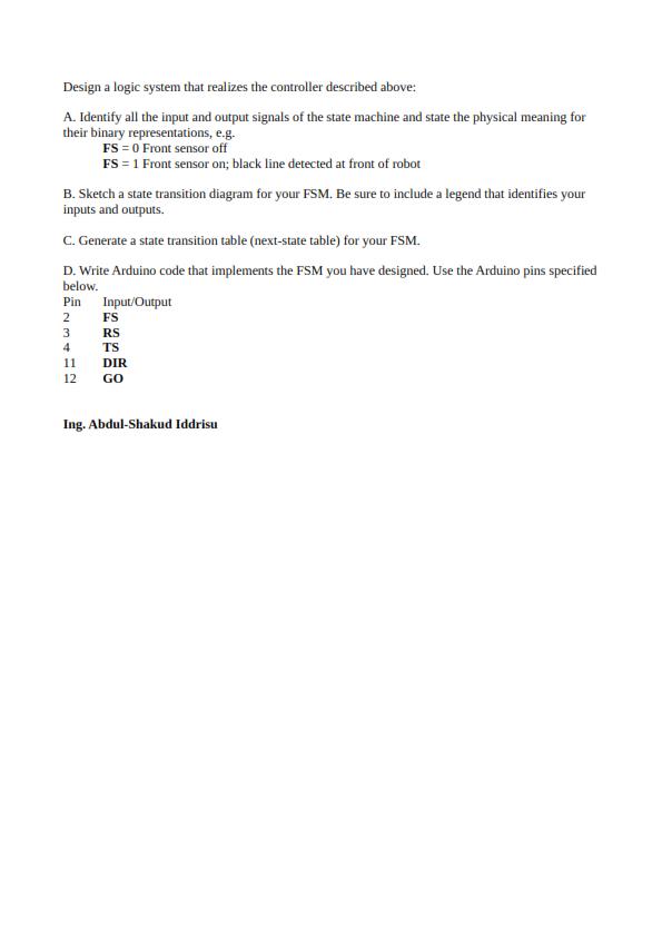
Design a logic system that realizes the controller described above: A. Identify all the input and output signals of the state machine and state the physical meaning for their binary representations, e.g. FS = 0 Front sensor off FS = 1 Front sensor on; black line detected at front of robot B. Sketch a state transition diagram for your FSM, Be sure to include a legend that identifies your inputs and outputs. C. Generate a state transition table (next-state table) for your FSM. D. Write Arduino code that implements the FSM you have designed. Use the Arduino pins specified below. Pin Input/Output 2 FS 3 RS 4 TS 11 DIR 12 GO Ing. Abdul-Shakud Iddrisu
Step by Step Solution
3.36 Rating (149 Votes )
There are 3 Steps involved in it

Get step-by-step solutions from verified subject matter experts