

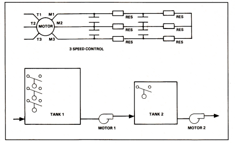
Question: Design a process control circuit to operate the tank level system shown in Figure 2-A5 according to the following specifications: 1. Power to system shall
Design a process control circuit to operate the tank level system shown in Figure 2-A5 according to the following specifications: 1. Power to system shall be by standard means at 480 V primary and 120-V control. 2. A three-phase z-hp motor (number 1) is controlled by a relay on the secondary side of a transformer. The relay is controlled manually and automatically using a selector switch. 3. The motor is three-speed resistor controlled and is coupled to a fluid pump in an automatic liquid-controlled system. The selector switch in automatic position operates with a float switch. As fluid rises; a first float switch (FS1) operates to energize control relay 1. This starts the motor in slow speed and energizes a timing relay (TR1). If the motor speed is too slow to effect proper fluid delivery, liquid level in the tank will eventually close a second float switch. This energizes control relay 2 and the now-closed contacts of TRl1 operate the first set of contacts (1A) to shunt out the first bank of resistors and also energize a second time-delay relay. If speed is still not enough, this process occurs once more. 4. There is a three-phase, .75-hp motor (number 2) also wired to the primary side. It will operate in forward either when the float control in tank 2 indicates that the fluid level is high enough to begin pumping or by manual start. 5. Motor 2 must be able to be reversed regardless of the tank 2 level. Motor 1 must be stopped during this operation.
Include the following information on the assignment: I. Lay out the complete control diagram to meet the objectives listed above.
II. Include a brief operating sequence. III. Identify numerically each wired connection between all terminals (interwire numbering) required to complete the circuit. IV. Identify location of all contacts for each coil.
MOTOR 1 MOTOR 2 MOTOR 1 MOTOR 2
Step by Step Solution
There are 3 Steps involved in it

Get step-by-step solutions from verified subject matter experts