

Question: Design the four bit left and right shift register using XilinxVivado (VERILOG source file). Use four D flip-flops, one for eachbit of storage. The clock
Design the four bit left and right shift register using XilinxVivado (VERILOG source file). Use four D flip-flops, one for eachbit of storage. The clock input should be connected to a pushbutton so that every time the push button is pressed, the shiftregisterseesaclockpulsetoeitherloaddataintoitorshiftitsdataleftorright.Switchesare notorious of producing many edge transitions when they go from?on? to ?off? or ?off? to ?on? (sometimes). These extra edgesresult in extra clock edges to the shift register clock input whena single clock edge is expected. Since the D flip-flops are edgetriggered in the shift register, these extra edges result in theshifting of its bits by more than one bit at atime.
I have completed the procedural code and was given a propersimulation code however my waveform is not working as itshould.
This is my waveform,
![Name load_t 0 Q_t[3:0] e 1 [3] 1 [2] 1 [1] [0]](https://dsd5zvtm8ll6.cloudfront.net/si.experts.images/questions/2022/11/6380715c2f6c4_0116380715bd7774.jpg)
This is the correct wave form,
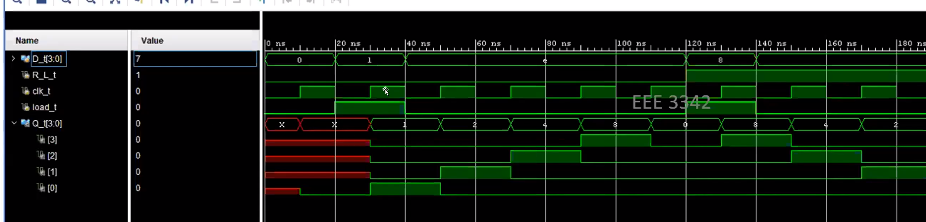
Everything is the same on my waveform, aside from the outputline.
This is my code,
module shift_register( input load, input clock, input R_L, input [3:0] D, //Data? output reg [3:0] Q
);
always @(posedge clock) if(load==1)begin Q[3]
Q[2]
Q[1]
Q[0]
Q[2]
Q[1]
Q[0]
Q[2]
Q[1]
Q[0]
This is the sim (I cannot change this):
module shift_register_sim(
);reg [3:0]D_t;reg R_L_t;reg clk_t;reg load_t;wire [3:0]Q_t;
shift_reg UUT(.D(D_t),.R_L(R_L_t),.clock(clk_t),.load(load_t),.Q(Q_t)
);
initial beginclk_t =0;
D_t =0;R_L_t = 0;load_t =0;#20;
D_t =4'b0001;R_L_t = 0;load_t =1;
#20;D_t =4'b1110;R_L_t = 0;load_t =0;#20;D_t =4'b1110;R_L_t = 0;load_t =0;
#20;D_t =4'b1110;R_L_t = 0;load_t =0;#20;D_t =4'b1110;R_L_t = 0;load_t =0;
#20;D_t =4'b1000;R_L_t = 1;load_t =1;
#20;D_t =4'b0111;R_L_t = 1;load_t =0;#20;D_t =4'b0111;R_L_t = 1;load_t =0;
#20;D_t =4'b0111;R_L_t = 1;load_t =0;#20;D_t =4'b0111;R_L_t = 1;load_t =0;
end
always #10 clk_t = ~clk_t;endmodule
Name load_t 0 Q_t[3:0] e 1 [3] 1 [2] 1 [1] [0] Value 0 10 ns X 50 ns 1 100 ns 8 150 ns 200 ns 250 ns e 300 ns 350 ns
Step by Step Solution
3.39 Rating (152 Votes )
There are 3 Steps involved in it

Get step-by-step solutions from verified subject matter experts