

Question: Details for the project to be prepared using the PIC 16F877A microcontroller given below. 7Seg Display to the inputs of the C port (RCO-RC6) of
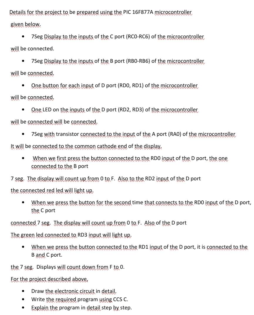
Details for the project to be prepared using the PIC 16F877A microcontroller given below. 7Seg Display to the inputs of the C port (RCO-RC6) of the microcontroller will be connected. 7Seg Display to the inputs of the B port (RBO-RB6) of the microcontroller will be connected, . One button for each input of D port (RDO, RD1) of the microcontroller will be connected, . One LED on the inputs of the D port (RD2, RD3) of the microcontroller will be connected will be connected. . 7Seg with transistor connected to the input of the A port (RAO) of the microcontroller It will be connected to the common cathode end of the display. O When we first press the button connected to the RDO input of the D port, the one connected to the B port 7 seg. The display will count up from 0 to F. Also to the RD2 input of the D port the connected red led will light up, When we press the button for the second time that connects to the RDO input of the D port, the C port connected 7 seg. The display will count up from 0 to F. Also of the D port The green led connected to RD3 input will light up. When we press the button connected to the RD1 input of the D port, it is connected to the B and C port. the 7 seg. Displays will count down from F to 0. For the project described above, Draw the electronic circuit in detail, Write the required program using CCS C. Explain the program in detail step by step. . Details for the project to be prepared using the PIC 16F877A microcontroller given below. 7Seg Display to the inputs of the C port (RCO-RC6) of the microcontroller will be connected. 7Seg Display to the inputs of the B port (RBO-RB6) of the microcontroller will be connected, . One button for each input of D port (RDO, RD1) of the microcontroller will be connected, . One LED on the inputs of the D port (RD2, RD3) of the microcontroller will be connected will be connected. . 7Seg with transistor connected to the input of the A port (RAO) of the microcontroller It will be connected to the common cathode end of the display. O When we first press the button connected to the RDO input of the D port, the one connected to the B port 7 seg. The display will count up from 0 to F. Also to the RD2 input of the D port the connected red led will light up, When we press the button for the second time that connects to the RDO input of the D port, the C port connected 7 seg. The display will count up from 0 to F. Also of the D port The green led connected to RD3 input will light up. When we press the button connected to the RD1 input of the D port, it is connected to the B and C port. the 7 seg. Displays will count down from F to 0. For the project described above, Draw the electronic circuit in detail, Write the required program using CCS C. Explain the program in detail step by step
Step by Step Solution
There are 3 Steps involved in it

Get step-by-step solutions from verified subject matter experts