

Question: Develop the f o u t waveform for the circuit in Figure below, an 8 kHz square wave input is applied to the clock input
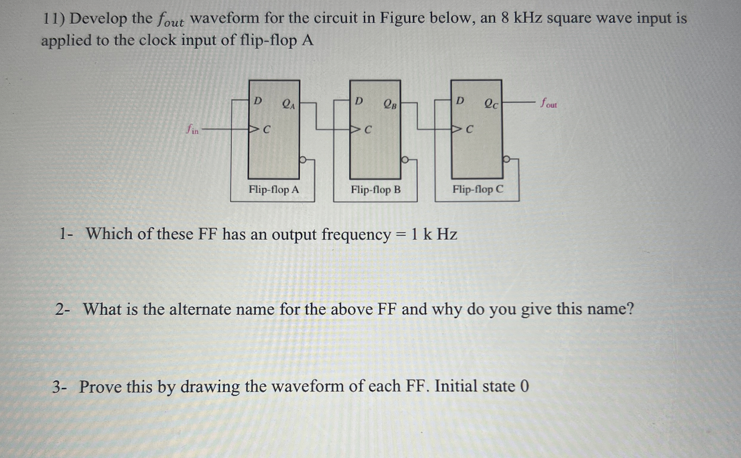
Develop the waveform for the circuit in Figure below, an kHz square wave input is applied to the clock input of flipflop A
Which of these FF has an output frequency
What is the alternate name for the above FF and why do you give this name?
Prove this by drawing the waveform of each FF Initial state
Step by Step Solution
There are 3 Steps involved in it
1 Expert Approved Answer
Step: 1 Unlock

Question Has Been Solved by an Expert!
Get step-by-step solutions from verified subject matter experts
Step: 2 Unlock
Step: 3 Unlock