

Question: Draw the bond graph for the lever system shown below. The lever of a length L has mass which is taken into account with the
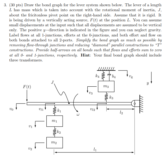
Draw the bond graph for the lever system shown below. The lever of a length
L has mass which is taken into account with the rotational moment of inertia, J
about the fricitonless pivot point on the righthand side. Assume that it is rigid. It
is being driven by a vertically acting source, Ft at the position L You can assume
small displacements at the input such that all displacements are assumed to be vertical
only. The positive ydirection is indicated in the figure and you can neglect gravity.
Label flows at all junctions, efforts at the junctions, and both effort and flow on
both bonds attached to all ports. Simplify the bond graph as much as possible by
removing flowthrough junctions and reducing diamond parallel constructions to T
constructions. Provide halfarrows on all bonds such that flows and efforts sum to zero
at all and junctions, respectively. Hint: Your final bond graph should include
three transformers.
Step by Step Solution
There are 3 Steps involved in it
1 Expert Approved Answer
Step: 1 Unlock

Question Has Been Solved by an Expert!
Get step-by-step solutions from verified subject matter experts
Step: 2 Unlock
Step: 3 Unlock