

Question: During the design process for this truss an alternative 'Configuration II ' was also considered. For this truss, nodes 1 , 2 , 3 and
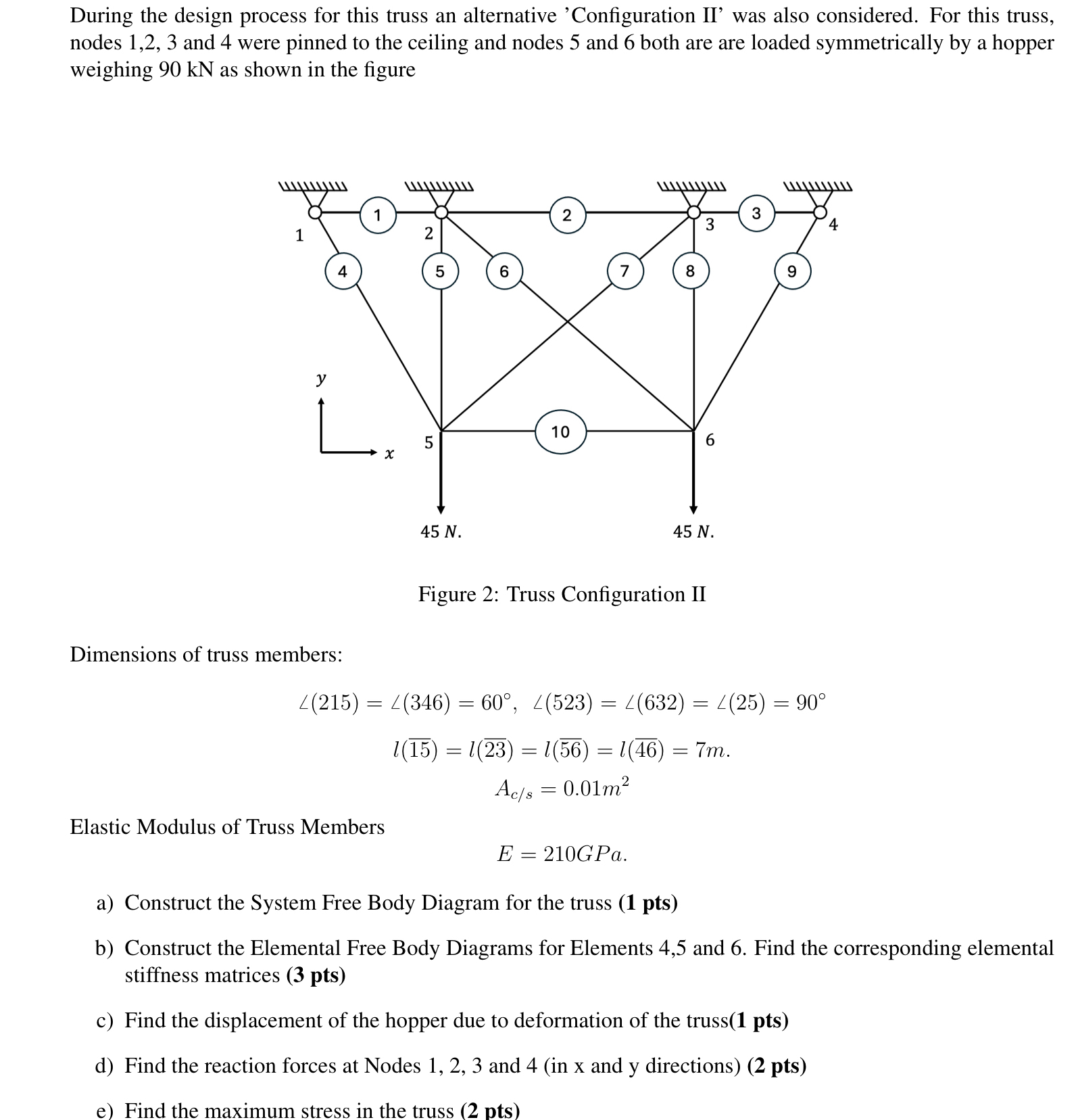
During the design process for this truss an alternative 'Configuration II was also considered. For this truss,
nodes and were pinned to the ceiling and nodes and both are are loaded symmetrically by a hopper
weighing kN as shown in the figure
Figure : Truss Configuration II
Dimensions of truss members:
Elastic Modulus of Truss Members
GPa
a Construct the System Free Body Diagram for the truss pts
b Construct the Elemental Free Body Diagrams for Elements and Find the corresponding elemental
stiffness matrices
c Find the displacement of the hopper due to deformation of the truss
d Find the reaction forces at Nodes and in x and y directions pts
e Find the maximum stress in the truss pts
Step by Step Solution
There are 3 Steps involved in it
1 Expert Approved Answer
Step: 1 Unlock

Question Has Been Solved by an Expert!
Get step-by-step solutions from verified subject matter experts
Step: 2 Unlock
Step: 3 Unlock