

Question: Dynamics and Control In this exercise you are going to perform system identification and implement a PD controller for a 1 degree - of -
Dynamics and Control
In this exercise you are going to perform system identification and implement a PD
controller for a degreeoffreedom robot manipulator.
Again you are provided with a C library containing a dynamic simulator and
a file in which you should implement the controller. For this part of the assign
ment, download the corresponding code and uncompress it The subdirectory
contains the following files:
Imakefile This file is used to create a machine specific Makefile by typing xmkmf
PDcontrol.c This is the file you have to edit in order to implement the controller
and to perform the experiments required for system identification.
liblibDyna This library contains the dynamic simulator.
In the file control.c make sure that you fill in the UTAID variable with your
UTA student ID number. The solution you will obtain depends on this number and
thus submissions using a different a ID number will likely yield wrong answers.
We will not accept answers derived from an incorrect student ID number.
The Dynamic Simulator
To generate the simulator you have to type make. This creates the simulator exe
cutable Dynamics. The simulator looks as follows:
The Slider on the bottom allows you to set the reference angle configuration
for your controller the reference velocity is always set to
Determine the dynamic parameters of the robot.
Here you are supposed to perform system identification to determine the
parameters required later to perform model compensation in your PD control
loop. The dynamic model of this single joint manipulator has the form
These are caused by the inertia of the arm the viscous friction in the joint
and by gravity
To determine these elements of the dynamics you have to perform experi
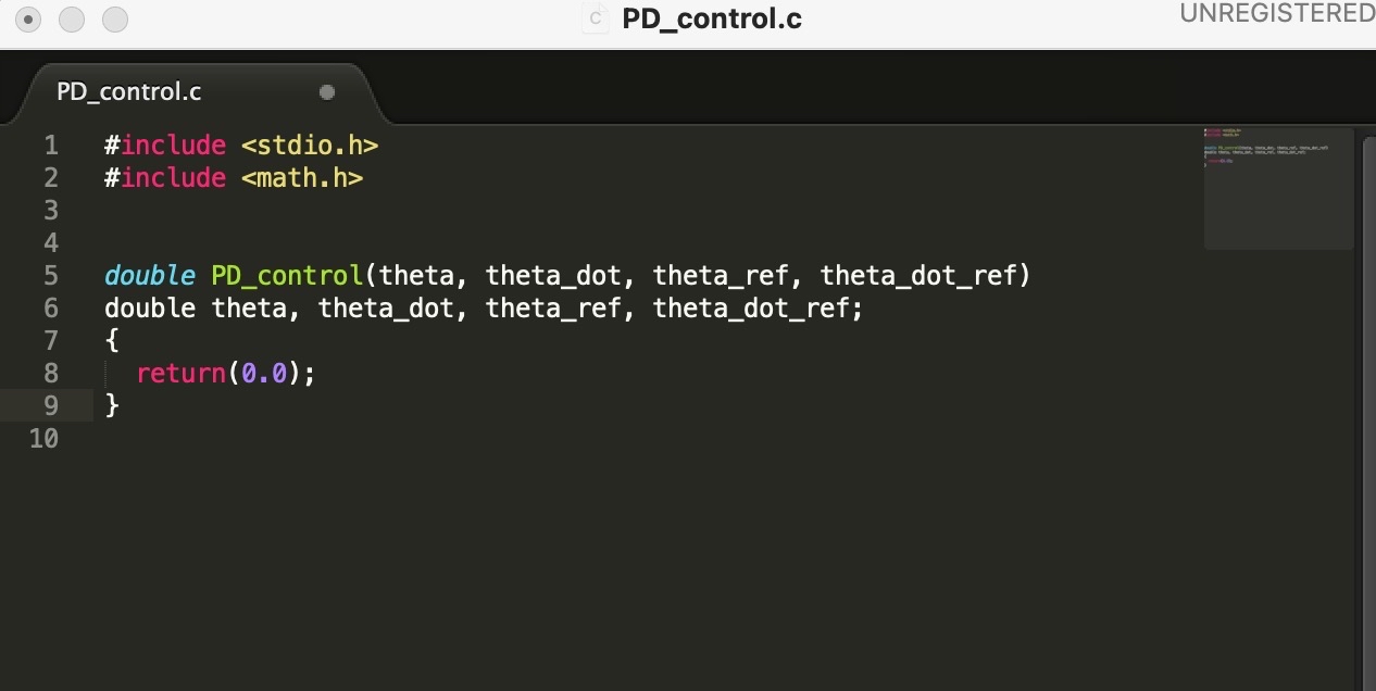
ments with the simulated robot. Your interface here is given in the function
PDcontrol which receives all relevant information from the robot system
and is called at a rate of Hz
double PDcontroltheta thetadot, thetaref, thetadotref
double theta, thetadot, thetaref, thetadotref;
return;
This function receives the current joint angle theta the corresponding ro
tational velocity thetadot the desired reference angle thetaref set using
the slider, and the reference velocity thetadotref The output of this func
tion should be the amount of torque you want to apply to the joint.
HINT: To perform system identification you want to collect this data and
analyze it in order to determine the system parameters
For this part of the assignment you should hand in the system parameters
found as well as a description of the method used to determine them.
Implement a PD controller with model compensation for the degreeof
freedom robot.
Using the parameters found above you should implement a PD controller
with model compensation for this robot. Use of the model will give the
system the appearance of a unitmass system without friction or gravity and
critically damped behavior should therefore be achieved by a choice of gains
where
For this part of the assignment you have to hand in the controller code you
implemented in the function control in the file control.c
PDcontrol.c
#include
Step by Step Solution
There are 3 Steps involved in it
1 Expert Approved Answer
Step: 1 Unlock

Question Has Been Solved by an Expert!
Get step-by-step solutions from verified subject matter experts
Step: 2 Unlock
Step: 3 Unlock