

Question: ECE4375-001/D01 Microprocessor Architecture HW2 NOTE: Submit the project directory in a ZIP file named using the following scheme: firstLast-HW2. Comment your code thoroughly and include
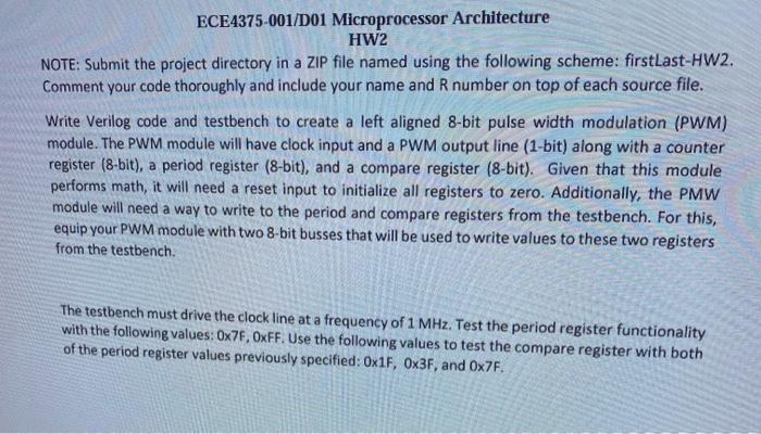
ECE4375-001/D01 Microprocessor Architecture HW2 NOTE: Submit the project directory in a ZIP file named using the following scheme: firstLast-HW2. Comment your code thoroughly and include your name and R number on top of each source file. Write Verilog code and testbench to create a left aligned 8-bit pulse width modulation (PWM) module. The PWM module will have clock input and a PWM output line (1-bit) along with a counter register (8-bit), a period register (8-bit), and a compare register (8-bit). Given that this module performs math, it will need a reset input to initialize all registers to zero. Additionally, the PMW module will need a way to write to the period and compare registers from the testbench. For this, equip your PWM module with two 8-bit busses that will be used to write values to these two registers from the testbench. The testbench must drive the clock line at a frequency of 1MHz. Test the period register functionality with the following values: 0x7F, OxFF. Use the following values to test the compare register with both of the period register values previously specified: 0x1F, 03F, and 07F
Step by Step Solution
There are 3 Steps involved in it

Get step-by-step solutions from verified subject matter experts