

Question: Educational Objective: The educational objective of this laboratory assignment is to gain experience programming the I / O pins on the TI MSP 4 3
Educational Objective:
The educational objective of this laboratory assignment is to gain experience programming the IO pins on the TI MSP microcontroller. The objective will be met by writing code that emulates the operation of a multifunction flashlight.
The multifunction flashlight works as follows:
The first time the power button is pushed, the LEDs turn on yellow
The second time the power button is pushed, the LEDs turn on red
The third time the power button is pushed, the LEDs flash green
The fourth time the power button is pushed, the LEDs turn off note that in a real flashlight the LEDs would be white, but we are using the expansion board that came in your kit
Background:
On the expansion board there are three clear LEDs that are able to display red, green or yellow. We will use these LEDs for this lab. The two LEDs that are parallel to the bottom of the board are referred to as main. They are tied together, and thus, controlled by the same pins. The other LED is referred to as side. The pinout for the
There are two pushbuttons on the board and we will be using the one on the top of the board, labeled 'car'. This pushbutton is connected to pin P The pushbutton is active low, meaning it drives a in the resting state and a when it is pushed.
PreLaboratory:
Read and follow the prelab instructions very carefully.
Review lectures and posted in MyCourses.
Open a new project in Code Composer Studio
Write the code for the MultiFunction Flashlight described above. You can use the outline labc posted in Mycourses as a guide if you would like.
Pay close attention to lecture for reading the input pushbutton
The code must be written using bit masking
CPET Lab MultiFunction Flashlight
Jeanne Christman
original version
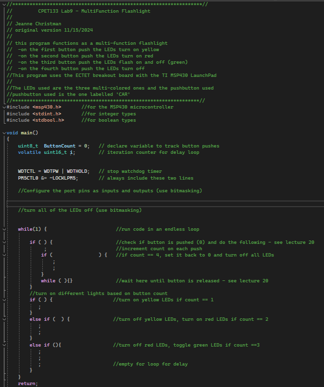
this program functions as a multifunction flashlight
on the first button push the LEDs turn on yellow
on the second button push the LEDs turn on red
on the third button push the LEDs flash on and off green
on the fourth button push the LEDs turn off
This program uses the ECTET breakout board with the TI MSP LaunchPad
The LEDs used are the three multicolored ones and the pushbutton used
pushbutton used is the one labelled 'CAR'
#include for the MSP microcontroller
#include for integer types
##include for boolean types
void main
uintt ButtonCount ; declare variable to track button pushes
volatile uintt i; iteration counter for delay loop
WDTCTL WDTPW wDTHOLD; stop watchdog timer
PHSCTLO & ~LOCKLPM; always include these two lines
Configure the port pins as inputs and outputs use bitmasking
turn all of the LEDs off use bitmasking
whilerun code in an endless loop
if check if button is pushed and do the following see lecture
; increment count on each push
if if count set it back to and turn off all LEDs
;
while wait here until button is released see lecture
turn on different lights based on button count
if turn on yellow LEDs if count
;
else if turn off yellow LEDs, turn on red LEDs if count
;
else if turn off red LEDs, toggle green LEDs if count
; ;
;
; empty for loop for delay
return;
Educational Objective:
The educational objective of this laboratory assignment is to gain experience programming the IO pins on the TI MSP microcontroller. The objective will be met by writing code that emulates the operation of a multifunction flashlight.
The multifunction flashlight works as follows:
The first time the power button is pushed, the LEDs turn on yellow
The second time the power button is pushed, the LEDs turn on red
The third time the power button is pushed, the LEDs flash green
The fourth time the power button is pushed, the LEDs turn off note that in a real flashlight the LEDs would be white, but we are using the expansion board that came in your kit
Background:
On the expansion board there are three clear LEDs that are able to display red, green or yellow. We will use these LEDs for this lab. The two LEDs that are parallel to the bottom of the board are referred to as main. They are tied together, and thus, controlled by the same pins. The other LED is referred to as side. The pinout for the
There are two pushbuttons on the board and we will be using the one on the top of the board, labeled 'car'. This pushbutton is connected to pin P The pushbutton is active low, meaning it drives a in the resting state and a when it is pushed.
PreLaboratory:
Read and follow the prelab instructions very carefully.
Review lectures and posted in MyCourses.
Open a new project in Code Composer Studio
Write the code for the MultiFunction Flashlight described above. You can use
Step by Step Solution
There are 3 Steps involved in it
1 Expert Approved Answer
Step: 1 Unlock

Question Has Been Solved by an Expert!
Get step-by-step solutions from verified subject matter experts
Step: 2 Unlock
Step: 3 Unlock