Question: EE4368 Final Design Project Application Notes using AWR Microwave Office 1. Create a New Project in MWO. a) In Project Options, in Frequencies tab set
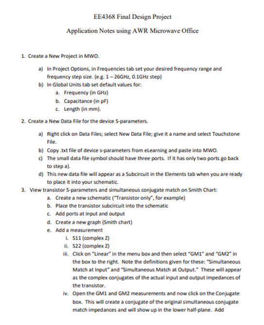
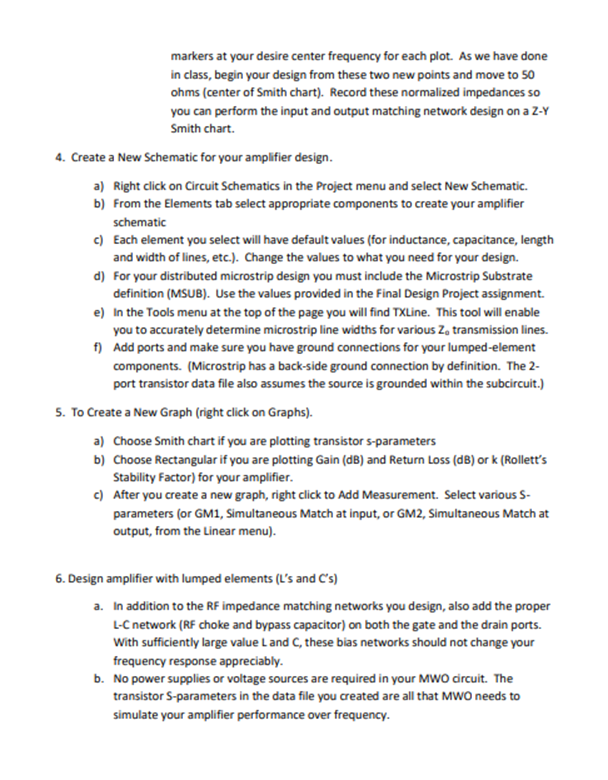
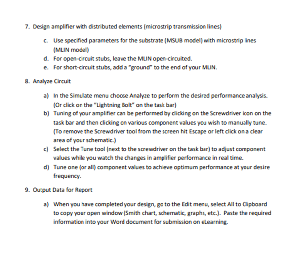
EE4368 Final Design Project Application Notes using AWR Microwave Office 1. Create a New Project in MWO. a) In Project Options, in Frequencies tab set your desired frequency range and frequency step size. (e.g. 1 - 26GH2, 0.1GHz step) b) In Global Units tab set default values for: a. Frequency (in GHz) b. Capacitance (in pF) . Length (in mm). 2. Create a New Data File for the device 5-parameters. a) Right click on Data Files; select New Data File; give it a name and select Touchstone File. b) Copy .txt file of device s-parameters from eLearning and paste into MWO. } The small data file symbol should have three ports. If it has only two ports go back to step a). d) This new data file will appear as a Subcircuit in the Elements tab when you are ready to place it into your schematic. 3. View transistor S-parameters and simultaneous conjugate match on Smith Chart: & Create a new schematic (\"Transistor only\markers at your desire center frequency for each plot. As we have done in class, begin your design from these two new points and move to 50 ohms (center of Smith chart). Record these normalized impedances so you can perform the input and output matching network design on a Z-Y Smith chart. 4. Create a New Schematic for your amplifier design. a) Right click on Circuit Schematics in the Project menu and select New Schematic. b) From the Elements tab select appropriate components to create your amplifier schematic c) Each element you select will have default values (for inductance, capacitance, length and width of lines, etc.). Change the values to what you need for your design. d) For your distributed microstrip design you must include the Microstrip Substrate definition (MSUB). Use the values provided in the Final Design Project assignment. e) In the Tools menu at the top of the page you will find TXLine. This tool will enable you to accurately determine microstrip line widths for various Z, transmission lines. f) Add ports and make sure you have ground connections for your lumped-element components. (Microstrip has a back-side ground connection by definition. The 2- port transistor data file also assumes the source is grounded within the subcircuit.) S. To Create a New Graph (right click on Graphs). a) Choose Smith chart if you are plotting transistor s-parameters b) Choose Rectangular if you are plotting Gain (dB) and Return Loss (dB) or k (Rollett's Stability Factor) for your amplifier. ) After you create a new graph, right click to Add Measurement. Select various 5- parameters (or GM1, Simultaneous Match at input, or GM2, Simultaneous Match at output, from the Linear menu). 6. Design amplifier with lumped elements (L's and C's) a. In addition to the RF impedance matching networks you design, also add the proper L-C network (RF choke and bypass capacitor) on both the gate and the drain ports. With sufficiently large value L and C, these bias networks should not change your frequency response appreciably. b. No power supplies or voltage sources are required in your MWO drcuit. The transistor S-parameters in the data file you created are all that MWO needs to simulate your amplifier performance over frequency. 7. Design amplifier with distributed elements (microstrip transmission lines) c. d. e Use specified parameters for the substrate (MSUB model) with microstrip lines (MLIN model) For open-circuit stubs, leave the MLIN open-circuited. For short-circuit stubs, add a \"ground\" to the end of your MLIN. 8. Analyze Circuit b) d) In the Simulate menu choose Analyze to perform the desired performance analysis. {Or click on the "Lightning Bolt on the task bar) Tuning of your amplifier can be performed by dicking on the Screwdriver icon on the task bar and then clicking on various component values you wish to manually tune. (To remove the Screwdriver tool from the screen hit Escape or left click on a clear area of your schematic.) Select the Tune tool (next to the screwdriver on the task bar) to adjust component values while you watch the changes in amplifier performance in real time. Tune one [or all) component values to achieve optimum performance at your desire frequency. 9. Output Data for Report When you have completed your design, go to the Edit menu, select All to Clipboard to copy your open window (Smith chart, schematic, graphs, etc.). Paste the required information into your Word document for submission on eLearning
Step by Step Solution
There are 3 Steps involved in it
1 Expert Approved Answer
Step: 1 Unlock
Question Has Been Solved by an Expert!
Get step-by-step solutions from verified subject matter experts
Step: 2 Unlock
Step: 3 Unlock
Students Have Also Explored These Related Law Questions!