

Question: Electric Circuits 7. A circuit is set up such that it has a current of 8.0 amps. What would be the new current if ....
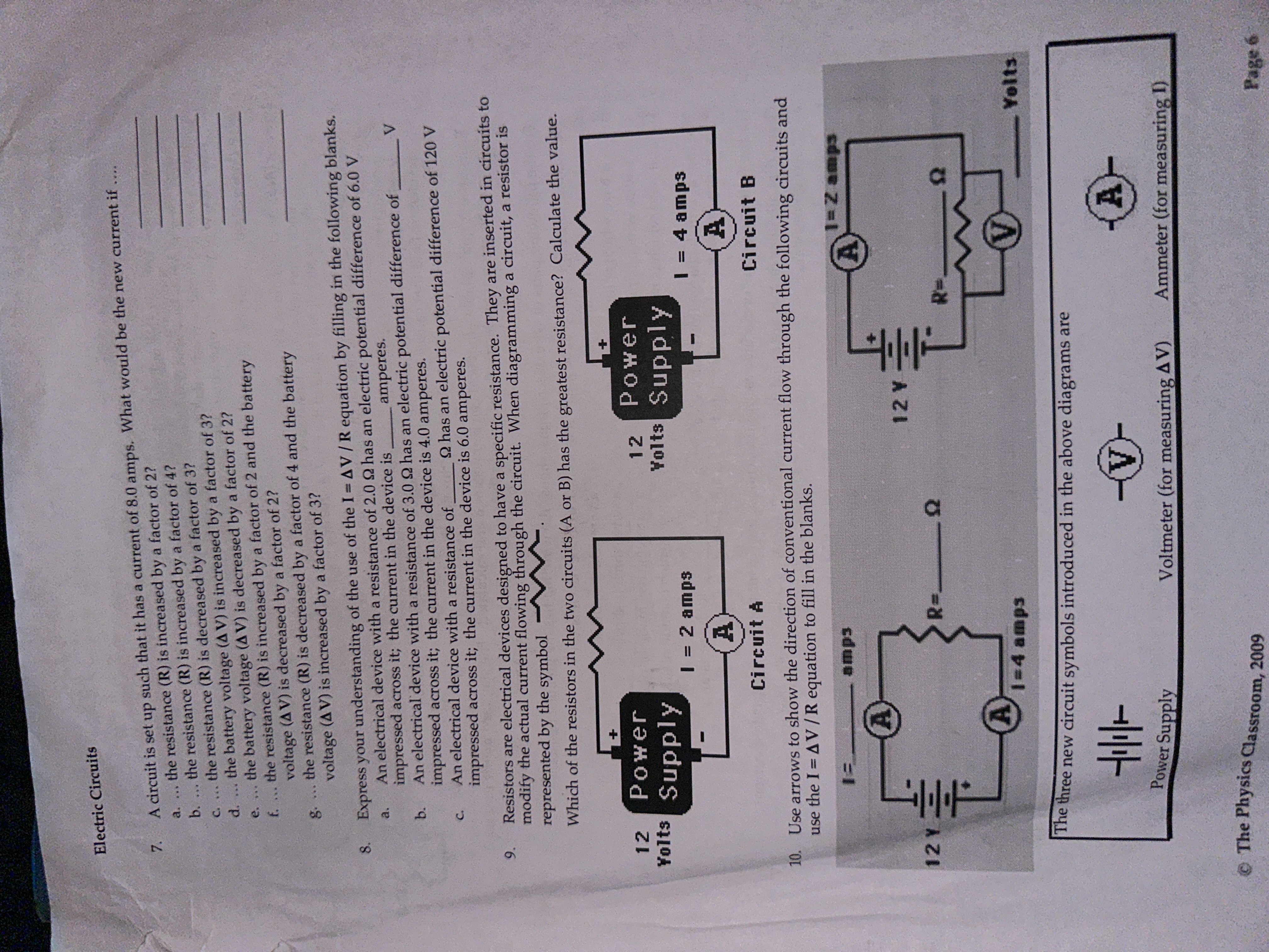
Electric Circuits 7. A circuit is set up such that it has a current of 8.0 amps. What would be the new current if .... a. ... the resistance (R) is increased by a factor of 2? b. ... the resistance (R) is increased by a factor of 4? c. ... the resistance (R) is decreased by a factor of 3? d. ... the battery voltage (A V) is increased by a factor of 3? e. ... the battery voltage (A V) is decreased by a factor of 2? f. ... the resistance (R) is increased by a factor of 2 and the battery voltage (AV) is decreased by a factor of 2? g. ... the resistance (R) is decreased by a factor of 4 and the battery voltage (A V) is increased by a factor of 3? 8. Express your understanding of the use of the I = AV / R equation by filling in the following blanks. a. An electrical device with a resistance of 2.0 9 has an electric potential difference of 6.0 V impressed across it; the current in the device is amperes. b. An electrical device with a resistance of 3.0 2 has an electric potential difference of V impressed across it; the current in the device is 4.0 amperes. C. An electrical device with a resistance of _ 2 has an electric potential difference of 120 V impressed across it; the current in the device is 6.0 amperes. 9. Resistors are electrical devices designed to have a specific resistance. They are inserted in circuits to modify the actual current flowing through the circuit. When diagramming a circuit, a resistor is represented by the symbol - Which of the resistors in the two circuits (A or B) has the greatest resistance? Calculate the value. 12 Power 12 Power Yolts Supply Yolts Supply 1 = 2 amps 1 = 4 amps Circuit A Circuit B 10. Use arrows to show the direction of conventional current flow through the following circuits and use the I = A V / R equation to fill in the blanks. 1= amps -Z amps 12 Y 12 Y 1=4 amps Yelts The three new circuit symbols introduced in the above diagrams are Power Supply Voltmeter (for measuring AV) Ammeter (for measuring 1) The Physics Classroom, 2009 Page 6
Step by Step Solution
There are 3 Steps involved in it

Get step-by-step solutions from verified subject matter experts