

Question: Embedded systems 4. Assume a 74MHz PIC24H processor is interfaced to LCD module with the following read cycle timing requirements: PWEH (min)=.150ns, TDSW (max)=.100ns TAS
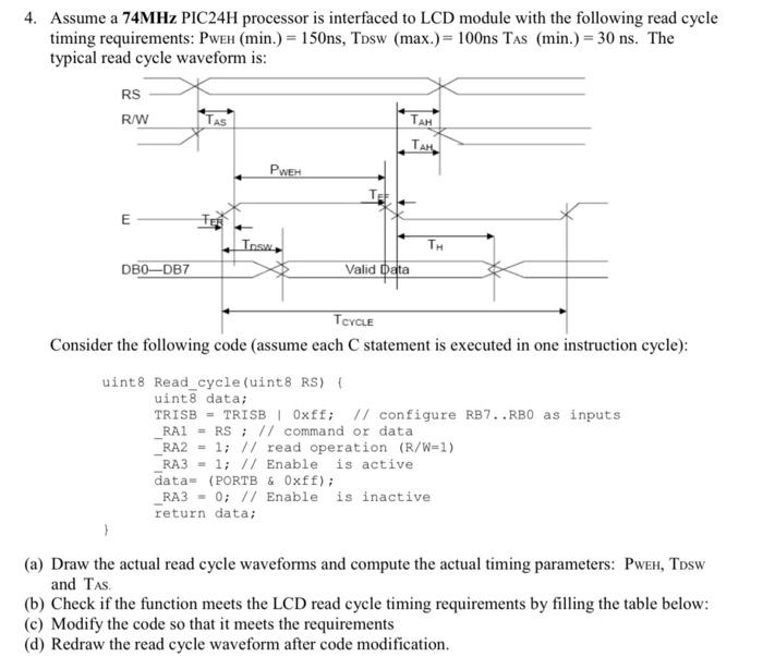
4. Assume a 74MHz PIC24H processor is interfaced to LCD module with the following read cycle timing requirements: PWEH (min)=.150ns, TDSW (max)=.100ns TAS (min)=.30ns. The typical read cycle waveform is: Consider the following code (assume each C statement is executed in one instruction cycle): uint8 Read_cycle (uint8 RS) 1 uint 8 data; TRISB = TRISB | 0xff; // configure RB7.RBO as inputs RA1 = RS; // command or data -RA2 =1;// read operation (R/W=1) -RA3 =1;// Enable is active data= (PORTB \& 0xff); -RA3 =0;// Enable is inactive return data; (a) Draw the actual read cycle waveforms and compute the actual timing parameters: PwEH, TDSW and TAS. (b) Check if the function meets the LCD read cycle timing requirements by filling the table below: (c) Modify the code so that it meets the requirements (d) Redraw the read cycle waveform after code modification
Step by Step Solution
There are 3 Steps involved in it

Get step-by-step solutions from verified subject matter experts