

Question: Energy conversion processes Assignment 2 : Waste heat recovery with ORC - process 1 INTRODUCTION In this assignment, we consider the conversion of industrial waste
Energy conversion processes
Assignment : Waste heat recovery with ORCprocess
INTRODUCTION
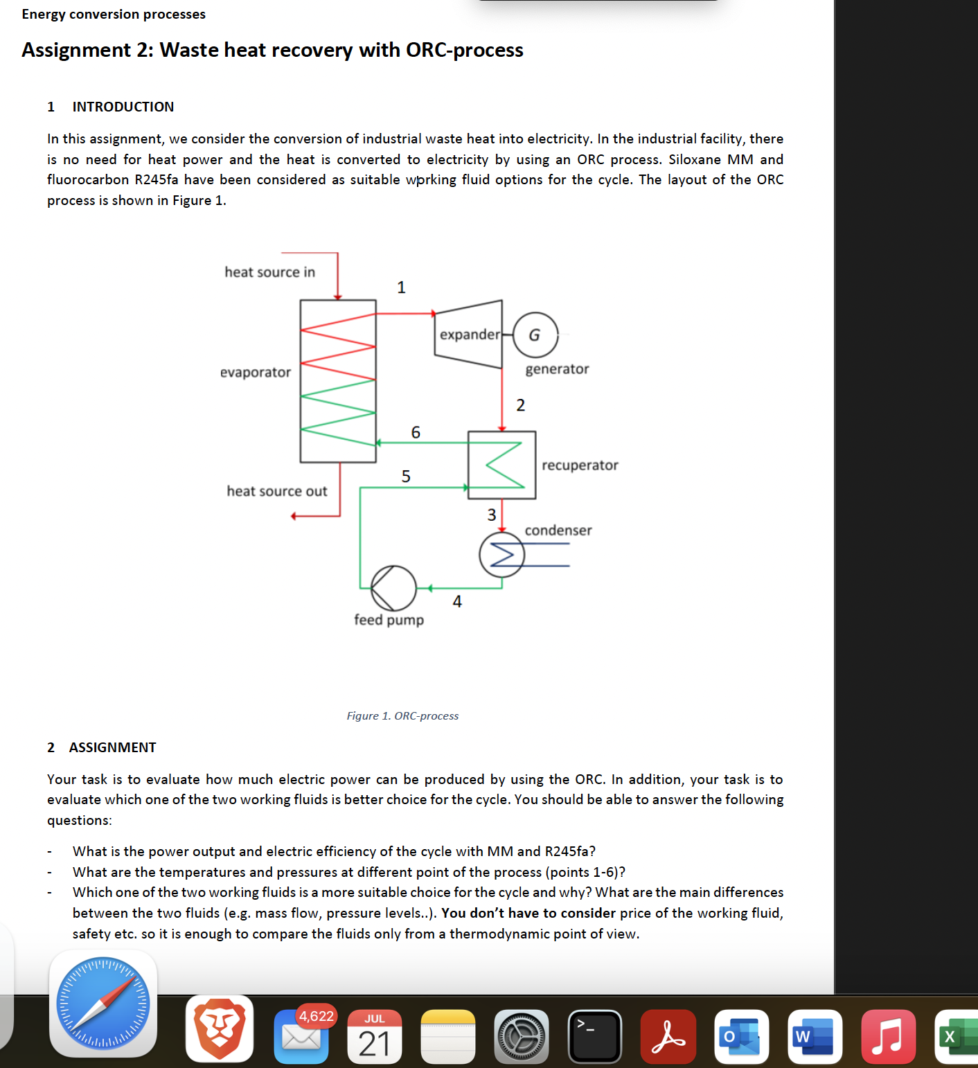
In this assignment, we consider the conversion of industrial waste heat into electricity. In the industrial facility, there is no need for heat power and the heat is converted to electricity by using an ORC process. Siloxane MM and fluorocarbon Rfa have been considered as suitable wprking fluid options for the cycle. The layout of the ORC process is shown in Figure
Figure ORCprocess
ASSIGNMENT
Your task is to evaluate how much electric power can be produced by using the ORC. In addition, your task is to evaluate which one of the two working fluids is better choice for the cycle. You should be able to answer the following questions:
What is the power output and electric efficiency of the cycle with MM and Rfa
What are the temperatures and pressures at different point of the process points
Which one of the two working fluids is a more suitable choice for the cycle and why? What are the main differences between the two fluids eg mass flow, pressure levels.. You don't have to consider price of the working fluid, safety etc. so it is enough to compare the fluids only from a thermodynamic point of view. CALCULATIONS
There are the log diagrams of the fluids given and you can use these diagrams in defining the required
thermodynamic properties. Note that the pressure is given in logarithmic scale and it represents the absolute
pressure.
You can make the following simplifications and assumptions:
No heat losses
No pressure losses
Working fluid is superheated by K before the expander point
Working fluid is saturated liquid at the condenser outletpoint
Temperature rise in feed pump is not significant lets assume T T
Density of the liquid is assumed as constant over the pump and the same density is used for both fluids to simplify
the calculation.
Only subcritical cycles are considered evaporator pressure and temperature must be kept below the critical point
of the fluid.
Initial values for calculations:
Specific heat capacity of the waste heat constant
Waste heat temperature at the evaporator outlet
Average liquid density in feed pump
Feed pump efficiency
Generator efficiency
Degree of recuperation
You can find rest of your initial values based on your surname.
HELP AND TIPS FOR SOLVING THE PROBLEM:
You can start by making a sketch of the cycle on log p h diagrams. First, select a suitable evaporating temperature. In
general the higher the evaporator temperature, the higher of the cycle efficiency and power output. Based on the
selected evaporating temperature you can define the corresponding pressure level pressure at points and You
can also define the expander inlet state now by taking into account the degree of superheating. Condensing
temperature is given in the initial values pressure at points and can be defined based on this information. To solve the expansion process in the expander, follow the constant entropy line from point to pressure this is
point s From this point you can define the expander isentropic outlet enthalpy Based on the turbineexpander
efficiency and the isentropic enthalpy change h can be solved.
The enthalpy change in feed pump can be solved as the condensing pressure and evaporation pressure are known:
Working fluid temperature at point can be solved from the definition of the degree of recuperation:
When h and h are known, you can solve and draw the temperature diagram of the evaporator and also solve the
pinch point. Look example from the ORC exercises remember to take into account also the superheating and liquid
preheating in the recuperator If the temperature differences between the working fluid and waste heat source are
large, you can increase the evaporation pressure and recalculate the cycle. The evaporator heat rate can be calculated
by using following equation:
FINAL REPORT AND OTHER INITIAL VALUES
Your final report should include the following information:
Your initial values
The most important equations you have been using
Results in a table including the process values, power output, turbine power, feed pump power and cycle
efficiency
Log drawings with the processes illustrated
Evaporator temperature diagram heat power on axis and pinch point temperature difference
Selection of working fluid. Which one of the two working fluids seems to be a better choice and why? What
Step by Step Solution
There are 3 Steps involved in it
1 Expert Approved Answer
Step: 1 Unlock

Question Has Been Solved by an Expert!
Get step-by-step solutions from verified subject matter experts
Step: 2 Unlock
Step: 3 Unlock