

Question: Enter the RISC - V instructions shown below into the Editor window. When you are finished, use the Simulator window to assemble your program using
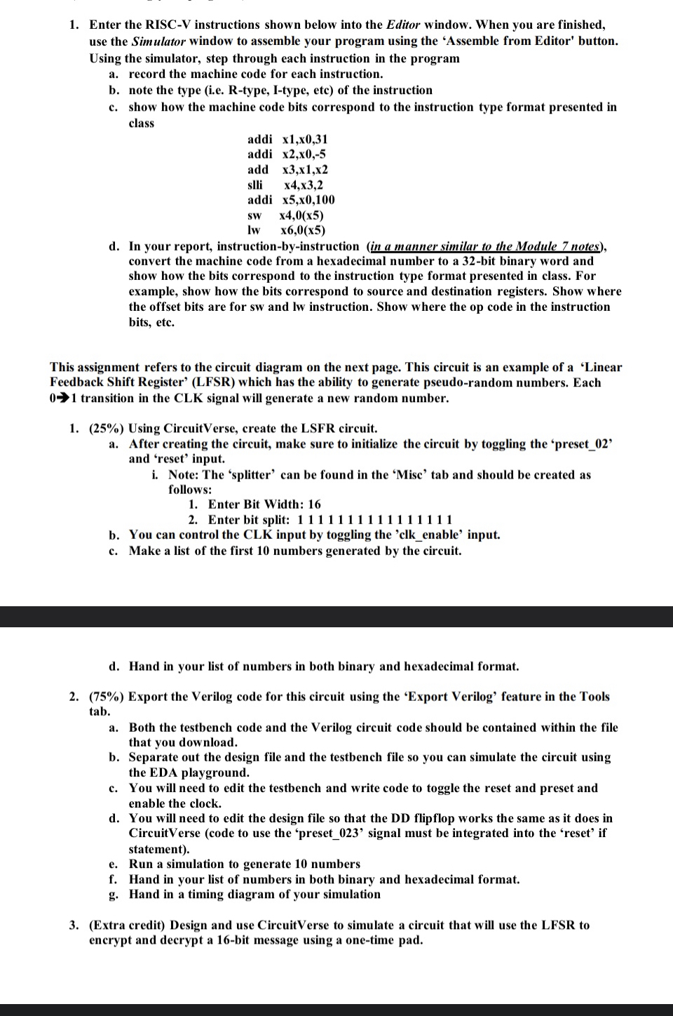
Enter the RISCV instructions shown below into the Editor window. When you are finished, use the Simulator window to assemble your program using the 'Assemble from Editor' button. Using the simulator, step through each instruction in the program
a record the machine code for each instruction.
b note the type ie Rtype, Itype, etc of the instruction
c show how the machine code bits correspond to the instruction type format presented in class
addi
addi
add
slli
addi
d In your report, instructionbyinstruction in a manner similar to the Module notes convert the machine code from a hexadecimal number to a bit binary word and show how the bits correspond to the instruction type format presented in class. For example, show how the bits correspond to source and destination registers. Show where the offset bits are for sw and lw instruction. Show where the op code in the instruction bits, etc.
This assignment refers to the circuit diagram on the next page. This circuit is an example of a 'Linear Feedback Shift Register' LFSR which has the ability to generate pseudorandom numbers. Each transition in the CLK signal will generate a new random number.
Using CircuitVerse, create the LSFR circuit.
a After creating the circuit, make sure to initialize the circuit by toggling the 'preset and 'reset' input.
i Note: The 'splitter' can be found in the 'Misc' tab and should be created as follows:
Enter Bit Width:
Enter bit split:
b You can control the CLK input by toggling the clkenable' input.
c Make a list of the first numbers generated by the circuit.
d Hand in your list of numbers in both binary and hexadecimal format.
Export the Verilog code for this circuit using the 'Export Verilog' feature in the Tools tab.
a Both the testbench code and the Verilog circuit code should be contained within the file that you download.
b Separate out the design file and the testbench file so you can simulate the circuit using the EDA playground.
c You will need to edit the testbench and write code to toggle the reset and preset and enable the clock.
d You will need to edit the design file so that the DD flipflop works the same as it does in CircuitVerse code to use the 'preset signal must be integrated into the 'reset' if statement
e Run a simulation to generate numbers
f Hand in your list of numbers in both binary and hexadecimal format.
g Hand in a timing diagram of your simulation
Extra credit Design and use CircuitVerse to simulate a circuit that will use the LFSR to encrypt and decrypt a bit message using a onetime pad.
Step by Step Solution
There are 3 Steps involved in it
1 Expert Approved Answer
Step: 1 Unlock

Question Has Been Solved by an Expert!
Get step-by-step solutions from verified subject matter experts
Step: 2 Unlock
Step: 3 Unlock