

Question: Block diagram of a regulator control system is shown in Fig. 1. ! T R(S)+ E(S) i. ii. K 111. GZOH Fig. I 1
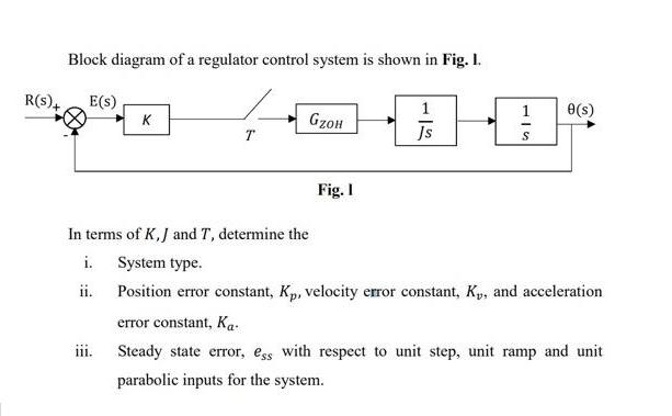
Block diagram of a regulator control system is shown in Fig. 1. ! T R(S)+ E(S) i. ii. K 111. GZOH Fig. I 1 Js In terms of K, J and T, determine the System type. Position error constant, Kp, velocity error constant, Ky, and acceleration error constant, Ka Steady state error, ess with respect to unit step, unit ramp and unit parabolic inputs for the system. 0(s)
Step by Step Solution
3.40 Rating (147 Votes )
There are 3 Steps involved in it
Based on the block diagram of the regulator control system provided we can analyze the system type error constants Kp Kv Ka and the steadystate error ... View full answer

Get step-by-step solutions from verified subject matter experts