

Question: Example 5 . 2 . 1 An electronic control system for an automobile engine is to be mounted on top of the fender inside the
Example
An electronic control system for an automobile engine is to be mounted on top of the fender inside the engine compartment of the automobile as illustrated in Figure The control module electronically computes and controls the engine timing, fuelair mixture, and so on and completely controls the engine. To protect it from fatigue and breakage, it is desirable to isolate the module from the vibration induced in the car body by road and engine vibration, hence the module is mounted on an isolator. Design the isolator ie pick and if the mass of the module is kg and the dominant vibration of the fender is approximated by Here it is desired to keep the displacement of the module less than m at all times Once the design values for isolators are chosen, calculate the magnitude of the force transmitted to the module through the isolator.
Solution Since it is desired to keep the vibration of the module, less than m the response amplitude becomes The amplitude of is ; hence the desired displacement transmissibility ratio becomes
Examining the transmissibility curves of Figure yields several possible solutions for and A straight horizontal line through TR illustrated in Figure crosses at several values of and For instance, the curve intersects the
Sec. Vibration Isolation
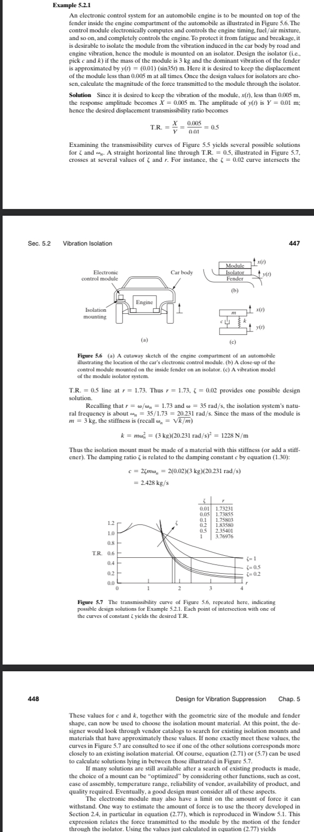
Figure a A cutaway sketch of the engine compartment of an automobile illustrating the location of the car's electronic control module. b A closeup of the control module mounted on the inside fender on an isolator. c A vibration model of the module isolator system.
TR line at Thus provides one possible design solution.
Recalling that and the isolation system's natural frequency is about Since the mass of the module is the stiffness is recall
Thus the isolation mount must be made of a material with this stiffness or add a stiffener The damping ratio is related to the damping constant by equation :
rugure ine transmissibuty curve of rigure repeated nere, inuscaung possible design solutions for Example Each point of intersection with one of the curves of constant yields the desired TR
Design for Vibration Suppression
Chap.
These values for and together with the geometric size of the module and fender shape, can now be used to choose the isolation mount material. At this point, the designer would look through vendor catalogs to search for existing isolation mounts and materials that have approximately these values. If none exactly meet these values, the curves in Figure are consulted to see if one of the other solutions corresponds more closely to an existing isolation material. Of course, equation or can be used to calculate solutions lying in between those illustrated in Figure
If many solutions are still available after a search of existing products is made, the choice of a mount can be "optimized" by considering other functions, such as cost ease of assembly, temperature range, reliability of vendor, availability of product, and quality required. Eventually, a good design must consider all of these aspects.
The electronic module may also have a limit on the amount of force it can withstand. One way to estimate the amount of force is to use the theory developed in Section in particular in equation which is reproduced in Window This expression relates the force transmitted to the module by the motion of the fender
through the isolator. Using the values just calculated in equation yields
Step by Step Solution
There are 3 Steps involved in it
1 Expert Approved Answer
Step: 1 Unlock

Question Has Been Solved by an Expert!
Get step-by-step solutions from verified subject matter experts
Step: 2 Unlock
Step: 3 Unlock