

Question: EXAMPLE 8 . 2 A domestic cold - water service system is shown in Figure 8 . 8 . The water main in the street
EXAMPLE
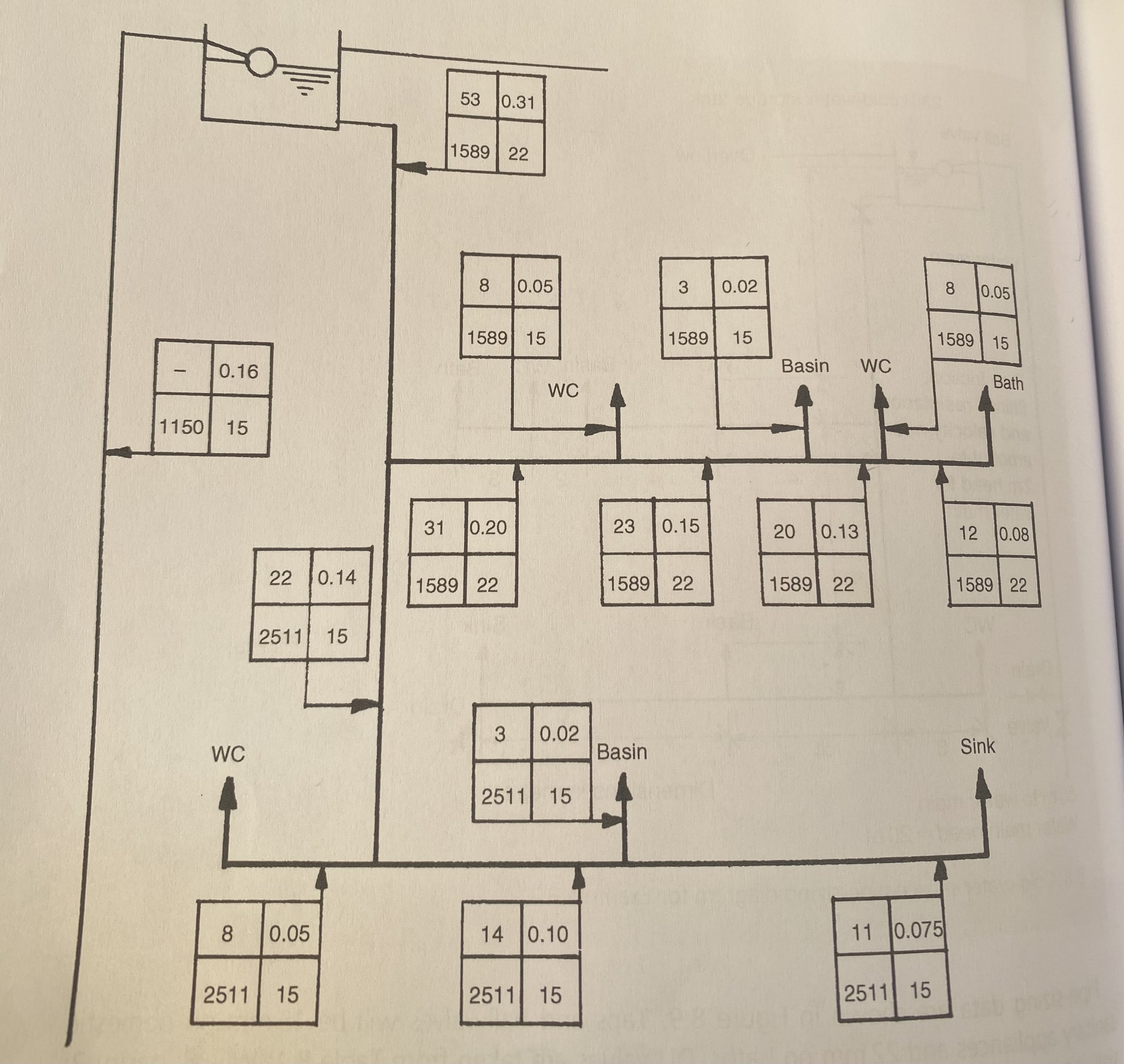
A domestic coldwater service system is shown in Figure The water main in the street
is m from the entry point shown and the supply authority provides a minimum static
pressure of m water gauge. The velocity energy and the frictional resistance at the ball
valve amount to m water gauge. Determine the pipe sizes.
I coldwater storage tank
m to water main
Dimensions in metres
Water main head
Coldwater service pipesizing diagram for Example
EXAMPLE
A domestic coldwater service system is shown in Figure The water main in the street
is m from the entry point shown and the supply authority provides a minimum static
pressure of m water gauge. The velocity energy and the frictional resistance at the ball
valve amount to m water gauge. Determine the pipe sizes.
I coldwater storage tank
m to water main
Dimensions in metres
Water main head
Coldwater service pipesizing diagram for Example The solution is there but my question is why they consider the pressure of the first floor and why the final pipe diameter is mm And from where they decided the discharge
Step by Step Solution
There are 3 Steps involved in it
1 Expert Approved Answer
Step: 1 Unlock

Question Has Been Solved by an Expert!
Get step-by-step solutions from verified subject matter experts
Step: 2 Unlock
Step: 3 Unlock