

Question: EXAMPLE 8.7 Engraving machine control system The engraving machine shown in Figure 8.32(a) uses two drive motors and associated lead screws to position the
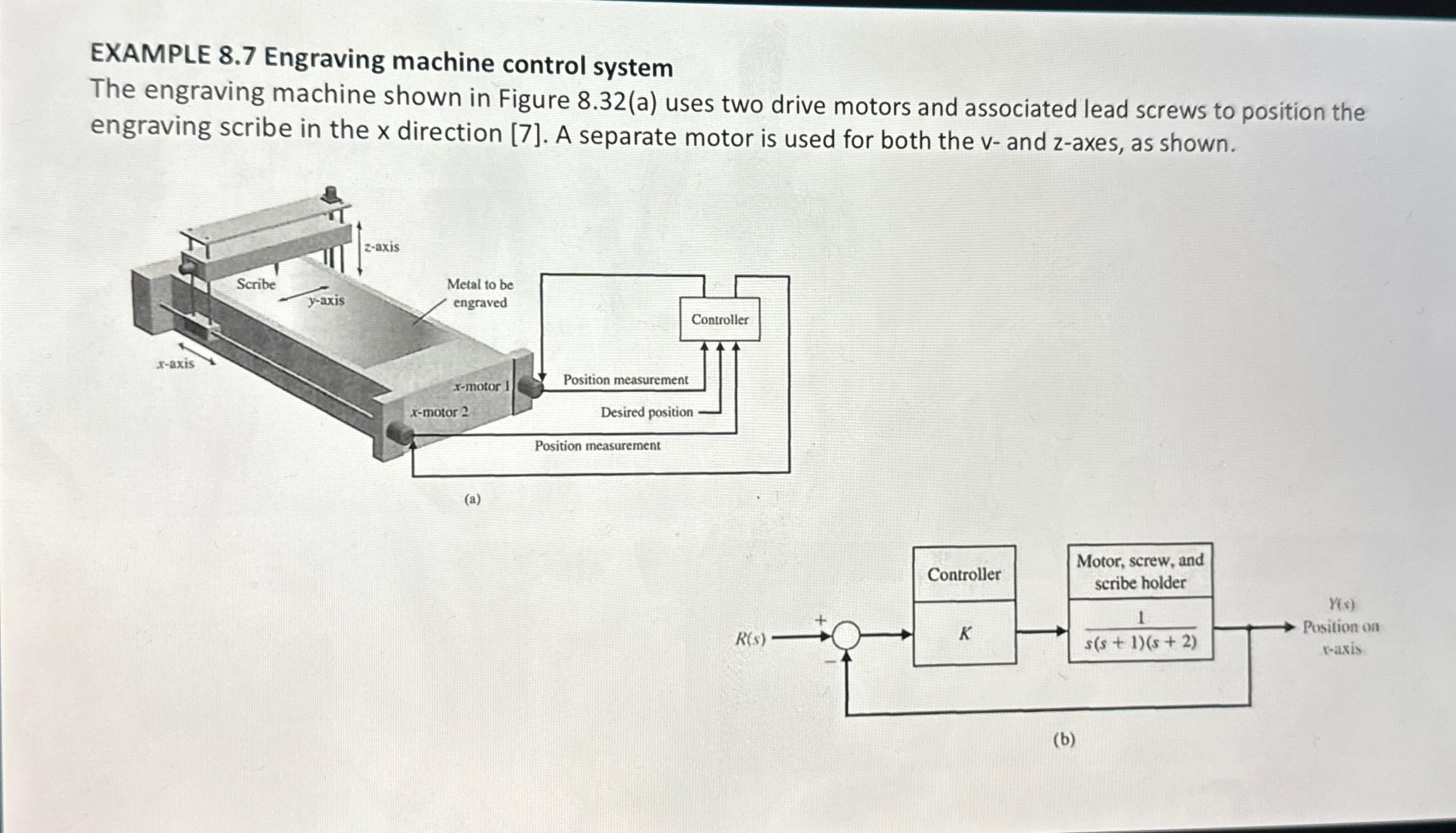
EXAMPLE 8.7 Engraving machine control system The engraving machine shown in Figure 8.32(a) uses two drive motors and associated lead screws to position the engraving scribe in the x direction [7]. A separate motor is used for both the v- and z-axes, as shown. x-axis Scribe y-axis z-axis Metal to be engraved Position measurement X-motor x-motor 2 Desired position Position measurement (a) Controller Controller Motor, screw, and scribe holder Y(s) 1 R(s) K Position on s(s + 1)(s+2) t-axis (b)
Step by Step Solution
There are 3 Steps involved in it
1 Expert Approved Answer
Step: 1 Unlock

Question Has Been Solved by an Expert!
Get step-by-step solutions from verified subject matter experts
Step: 2 Unlock
Step: 3 Unlock