

Question: Exercise 4. A bit-stream converter is a simple circuit that reads a sequence of bits, one at a time, and outputs another sequence of bits
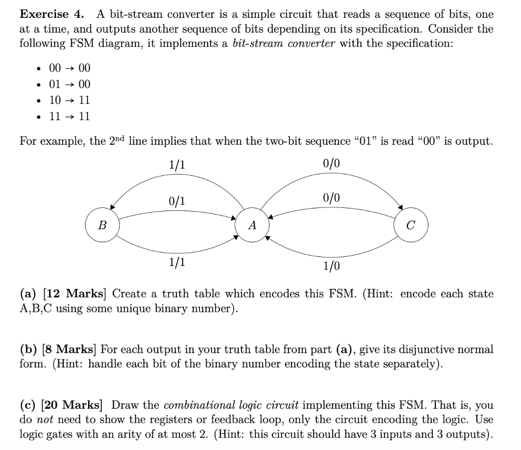
Exercise 4. A bit-stream converter is a simple circuit that reads a sequence of bits, one at a time, and outputs another sequence of bits depending on its specification. Consider the following FSM diagram, it implements a bit-stream converter with the specification: 00 00 01 00 10 11 11 + 11 For example, the 2nd line implies that when the two-bit sequence "01" is read "00" is output. 0/0 0/0 1/1 1/0 (a) [12 Marks Create a truth table which encodes this FSM. (Hint: encode each state A,B,C using some unique binary number). (b) [8 Marks] For each output in your truth table from part (a), give its disjunctive normal form. (Hint: handle each bit of the binary number encoding the state separately). (c) [20 Marks Draw the combinational logic circuit implementing this FSM. That is, you do not need to show the registers or feedback loop, only the circuit encoding the logic. Use logic gates with an arity of at most 2. (Hint: this circuit should have 3 inputs and 3 outputs). co mot need to show the registers or feedbac Exercise 4. A bit-stream converter is a simple circuit that reads a sequence of bits, one at a time, and outputs another sequence of bits depending on its specification. Consider the following FSM diagram, it implements a bit-stream converter with the specification: 00 00 01 00 10 11 11 + 11 For example, the 2nd line implies that when the two-bit sequence "01" is read "00" is output. 0/0 0/0 1/1 1/0 (a) [12 Marks Create a truth table which encodes this FSM. (Hint: encode each state A,B,C using some unique binary number). (b) [8 Marks] For each output in your truth table from part (a), give its disjunctive normal form. (Hint: handle each bit of the binary number encoding the state separately). (c) [20 Marks Draw the combinational logic circuit implementing this FSM. That is, you do not need to show the registers or feedback loop, only the circuit encoding the logic. Use logic gates with an arity of at most 2. (Hint: this circuit should have 3 inputs and 3 outputs). co mot need to show the registers or feedbac
Step by Step Solution
There are 3 Steps involved in it

Get step-by-step solutions from verified subject matter experts