

Question: Experiment 2: Basic Input/Output Operations for MSP430 (The Code for IAR MSP430 based C/C++ Programme) Theory: A. Pin Configuration of MSP430 The MSP430 microcontroller on
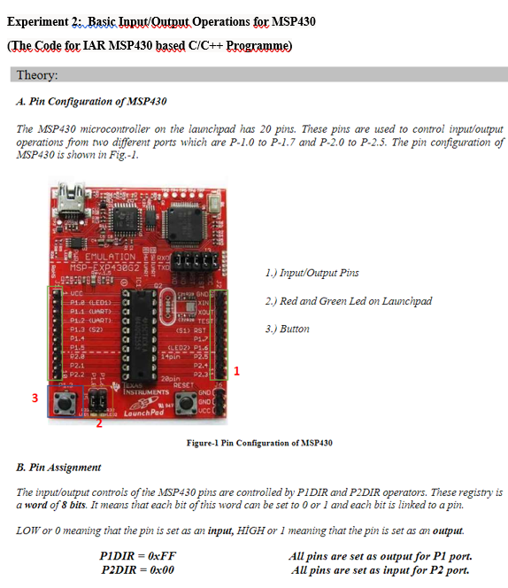
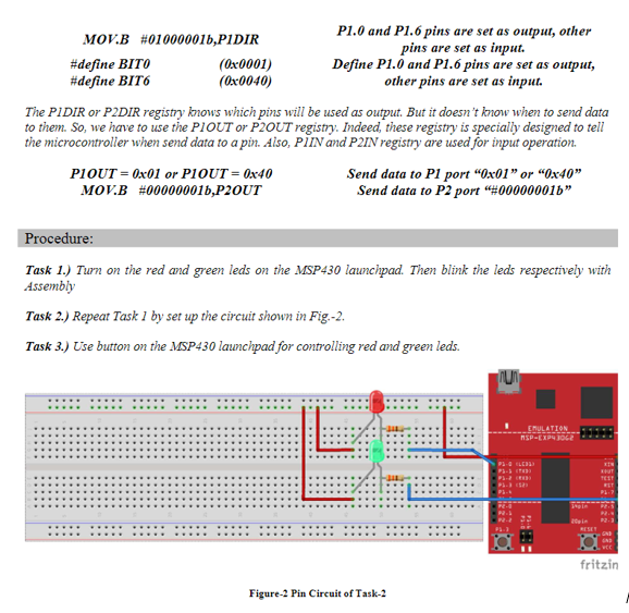
Experiment 2: Basic Input/Output Operations for MSP430 (The Code for IAR MSP430 based C/C++ Programme) Theory: A. Pin Configuration of MSP430 The MSP430 microcontroller on the launchpad has 20 pins. These pins are used to control input/output operations from two different ports which are P-1.0 to P-1.7 and P-2.0 to P-2.5. The pin configuration of MSP430 is shown in Fig.-1. , 1.) Input/Output Pins 3. GO 2.) Red and Green Led on Launchpad TES 22 _EMULATION MSP-EXP43862 TXO 9643919191 02 - UCC a Pie (LE01) CI XIN P11 (UART) CI XOUT P1.2-CUART P1.2 (S2) (S1) RST P1.4 P1.7 P1.5 (LED) 1.6 14pin 22.5 P2.1 P2.4 P2.2 P2.3 22pin P:3 RESET INSTRUMENTS GND GND LaunchPad Ucc 3.) Burton 3 Figure-1 Pin Configuration of MSP430 B. Pin Assignment The input/output controls of the MSP430 pins are controlled by PIDIR and P2DIR operators. These registry is a word of 8 bits. It means that each bit of this word can be set to 0 or 1 and each bit is linked to a pin. LOW or o meaning that the pin is set as an input, HGH or I meaning that the pin is set as an output. PIDIR =0xFF Au pins are set as output for P1 port. P2DIR = 0x00 All pins are set as input for P2 port. MOV.B #010000011,PIDIR P1.0 and P1.6 pins are set as output, other pins are set as input. #define BITO (0x0001) Define P1.0 and P1.6 pins are set as output, #define BIT6 (0x0040) other pins are set as input. The PIDIR or P2DIR registry knows which pins will be used as output. But it doesn't know when to send data to them. So, we have to use the PLOUT or P2OUT registry. Indeed, these registry is specially designed to tell the microcontroller when send data to a pin. Also, PIN and P2IN registry are used for input operation. PLOUT = 0x01 or PIOUT = 0x40 Send data to P1 port "0x01" or "0x40" MOV.B #000000016,P2OUT Send data to P2 port "#000000016" Procedure: Task 1.) Turn on the red and green leds on the MSP430 launchpad. Then blink the leds respectively with Assembly Task 2.) Repeat Task 1 by set up the circuit shown in Fig.-2. Task 3.) Use button on the MSP430 launchpad for controlling red and green leds. TU EMULATION SP-EXP4062 TELT ET DE fritzin Figure-2 Pin Circuit of Task-2
Step by Step Solution
There are 3 Steps involved in it

Get step-by-step solutions from verified subject matter experts