

Question: Experiment # 6 : Opamp Application Experiments Goals: The performance of the non - inverting and inverting voltage amplifiers will be examined. The investigation will
Experiment # : Opamp Application Experiments
Goals:
The performance of the noninverting and inverting voltage amplifiers will be examined.
The investigation will include the effect of feedback resistors on setting voltage gain, stability of gain with differing op amps, and input impedance and the concept of virtual ground.
Equipment:
Oscilloscope: Dual channel Digital Oscilloscope
Function Generator: Function Generator
Power Supply
or similar opamp
Breadboard
Resistors available in the laboratory
PartA: The Noninverting Voltage Amplifier Background Information:
The noninverting voltage amplifier is based on seriesparallel negative feedback. As the ideal voltagecontrolled voltage source, this amplifier exhibits high input impedance, low output impedance, and stable voltage gain. The voltage gain is set by the two feedback resistors, Ri and Rf
Schematics
Experimental Procedure:
The voltage gain of the noninverting amplifier can be determined accurately from the feedback resistors and Calculate the voltage gains for the amplifier of Fig. for the values specified, and record them in Table
Assemble the circuit of Fig. using the resistor.
Set the generator to a kHz sine wave, millivolts peak.
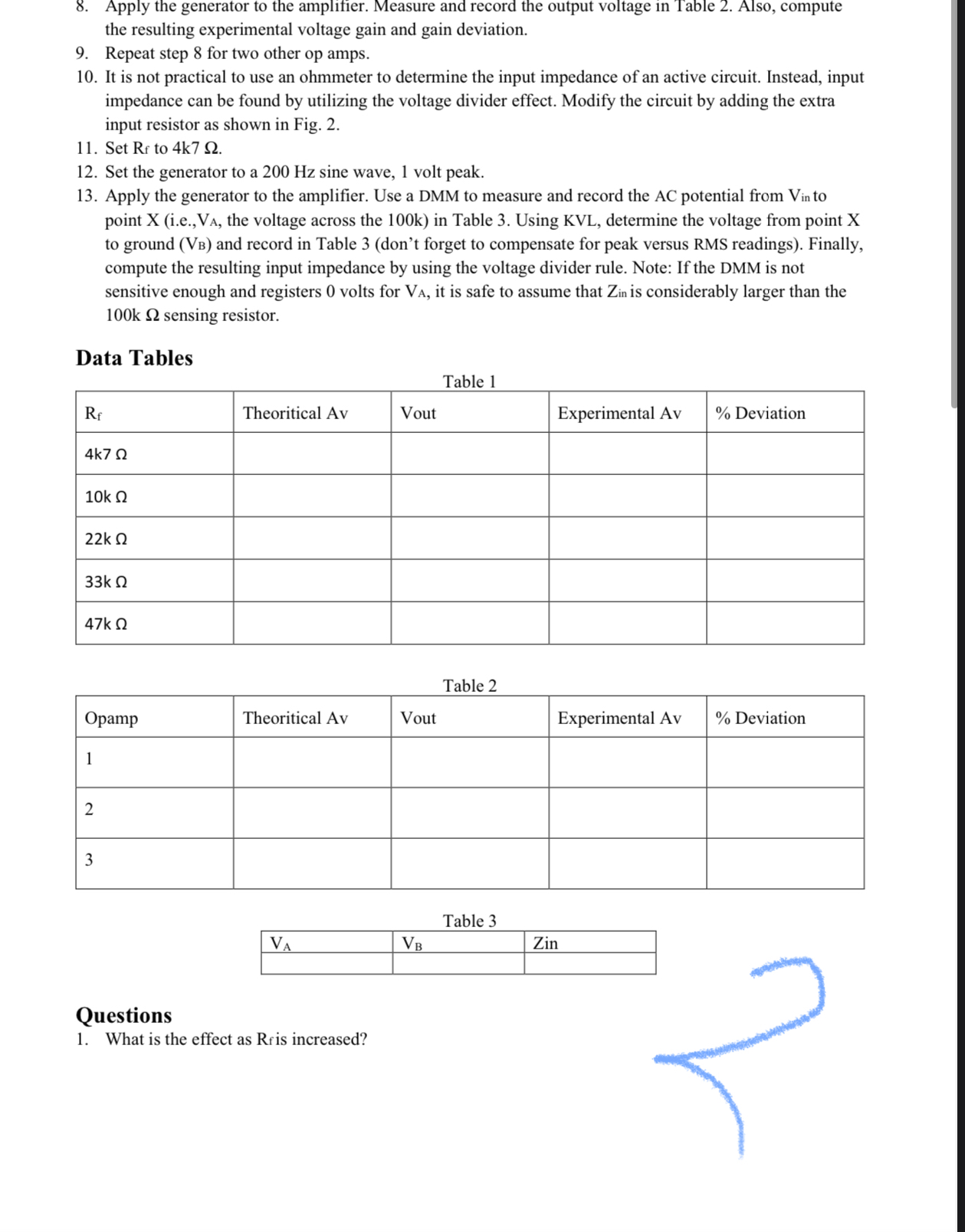
Apply the generator to the amplifier. Measure and record the output voltage in Table Also, compute the resulting experimental voltage gain and gain deviation.
Repeat step for the remaining Rfvalues in Table
For any given combination, the voltage gain should be stable regardless of the precise op amp used, even if it is of an entirely different model. To verify this, first set to
Set the generator to a kHz sine wave, millivolts peak.Apply the generator to the amplifier. Measure and record the output voltage in Table Also, compute the resulting experimental voltage gain and gain deviation.
Repeat step for two other op amps.
It is not practical to use an ohmmeter to determine the input impedance of an active circuit. Instead, input impedance can be found by utilizing the voltage divider effect. Modify the circuit by adding the extra input resistor as shown in Fig.
Set to
Set the generator to a Hz sine wave, volt peak.
Apply the generator to the amplifier. Use a DMM to measure and record the AC potential from to point X ie the voltage across the k in Table Using KVL determine the voltage from point X to ground and record in Table dont forget to compensate for peak versus RMS readings Finally, compute the resulting input impedance by using the voltage divider rule. Note: If the DMM is not sensitive enough and registers volts for it is safe to assume that is considerably larger than the sensing resistor.
Data Tables
Table
tableTheoritical AvVout,Experimental Av Deviation
Table
tableOpampTheoritical AvVout,Experimental Av Deviation
Table
tableZin
Questions
What is the effect as is increased?
Step by Step Solution
There are 3 Steps involved in it
1 Expert Approved Answer
Step: 1 Unlock

Question Has Been Solved by an Expert!
Get step-by-step solutions from verified subject matter experts
Step: 2 Unlock
Step: 3 Unlock