

Question: Experimental Layout: I. Experimentally build the inverting amplifier shown in Fig. 5 . 2 . with a gain of 1 2 . Use + -
Experimental Layout:
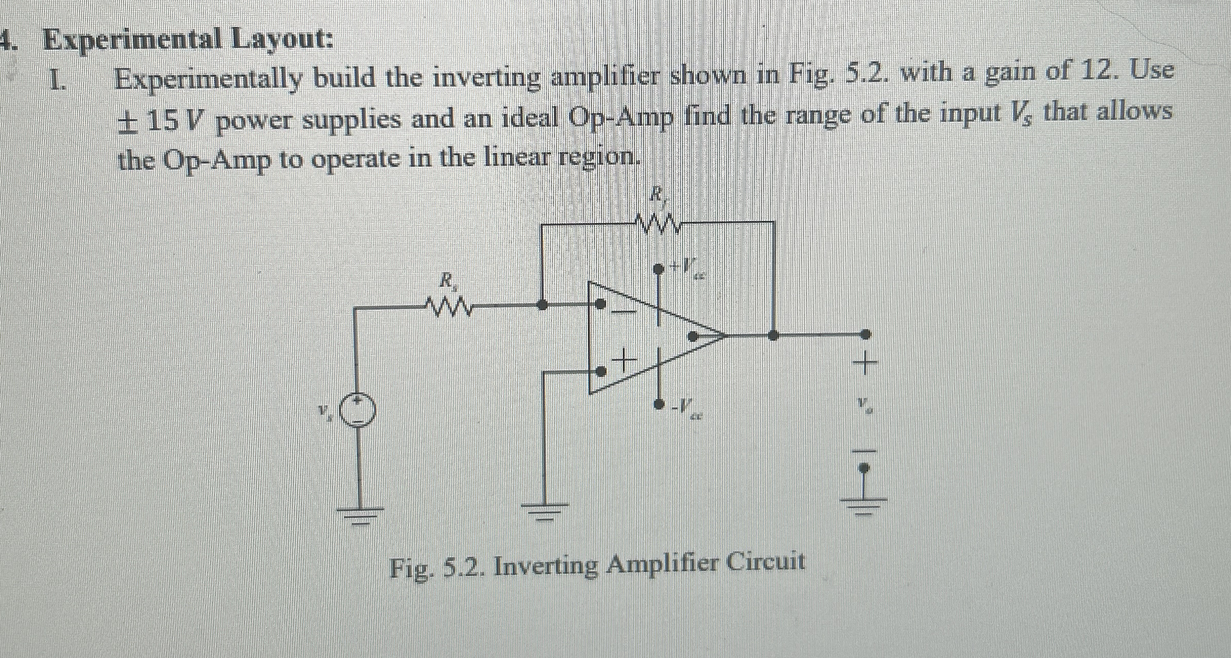
I. Experimentally build the inverting amplifier shown in Fig. with a gain of Use power supplies and an ideal Op Amp find the range of the input that allows the OpAmp to operate in the linear region.
Fig. Inverting Amplifier Circuit
Op amp LM
Can you do a step by step of this in multisim?
Step by Step Solution
There are 3 Steps involved in it
1 Expert Approved Answer
Step: 1 Unlock

Question Has Been Solved by an Expert!
Get step-by-step solutions from verified subject matter experts
Step: 2 Unlock
Step: 3 Unlock