

Question: Experimental Procedure Part 2: 1. Add a second power supply to the circuit as shown in Figure 3 R , K 2. Turn on the
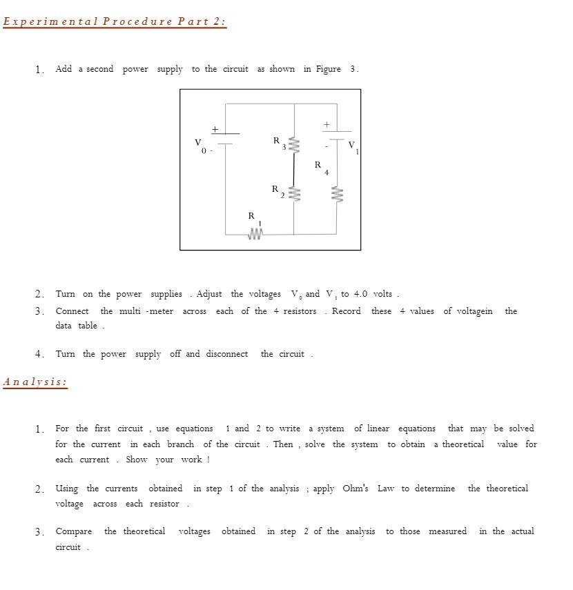

Experimental Procedure Part 2: 1. Add a second power supply to the circuit as shown in Figure 3 R , K 2. Turn on the power supplies . Adjust the voltages V, and V, to 4.0 volts 3. Connect the multi -meter across each of the 4 resistors . Record these 4 values of voltagein the data table . 4. Turn the power supply off and disconnect the circuit Analysis: 1. For the first circuit , use equations 1 and 2 to write a system of linear equations that may be solved for the current in each branch of the circuit . Then , solve the system to obtain a theoretical value for each current . Show your work ! 2. Using the currents obtained in step 1 of the analysis ; apply Ohm's Law to determine the theoretical voltage across each resistor 3. Compare the theoretical voltages obtained in step 2 of the analysis to those measured in the actual circuit
Step by Step Solution
There are 3 Steps involved in it

Get step-by-step solutions from verified subject matter experts