Question: fFor this lab, a hypothetical system is created so that a system curve can be calculated. Assume that you have a system that delivers water
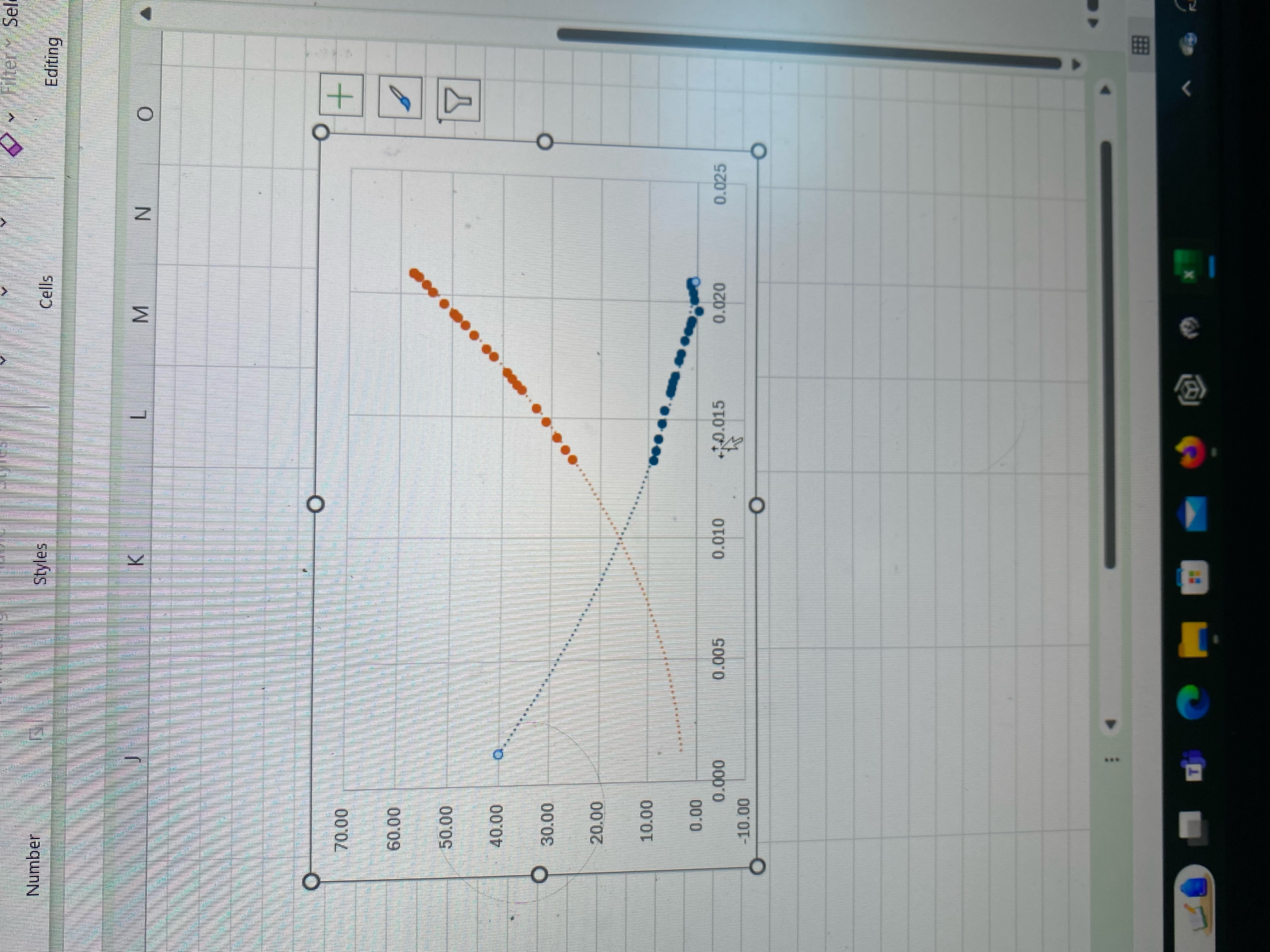
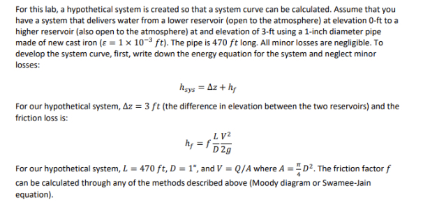
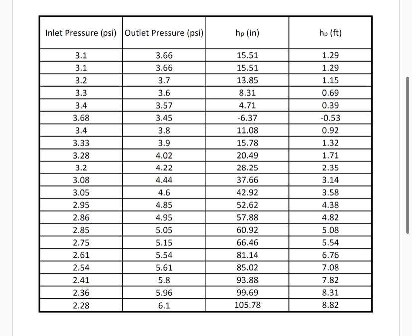
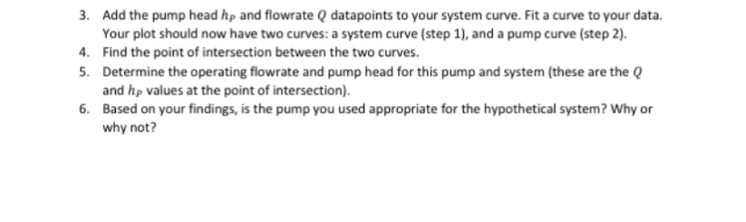
\fFor this lab, a hypothetical system is created so that a system curve can be calculated. Assume that you have a system that delivers water from a lower reservoir (open to the atmosphere) at elevation 0-ft to a higher reservoir (also open to the atmosphere) at and elevation of 3-ft using a 1-inch diameter pipe made of new cast iron ( = 1 % 1073 ft). The pipe is 470 ft long. All minor losses are negligible. To develop the system curve, first, write down the energy equation for the system and neglect minor losses: heys = Az + hy For our hypothetical system, Az = 3 ft (the difference in elevation between the two reservoirs) and the friction loss is: Ly? hy = f r=Ip3 > For our hypothetical system, L = 470 ft,D = 1", and V = /A where A = %Dz. The friction factor f can be calculated through any of the methods described above (Moody diagram or Swamee-Jain equation). \fAdd the pump head hp and flowrate datapoints to your system curve. Fit a curve to your data. Your plot should now have two curves: a system curve (step 1), and a pump curve (step 2). Find the point of intersection between the two curves. Determine the operating flowrate and pump head for this pump and system (these are the () and hp values at the point of intersection). Based on your findings, is the pump you used appropriate for the hypothetical system? Why or why not? Background A system curve is a curve used to display the relationship between the system's required head and its flowrate. Losses in a closed conduit system can be quantified by using the energy equation, shown below: _ Pout F?u t Pin , Vin s +zi,,+h,,-+2+zut+h,_+hT + Yy 29 Where h,, and hy are the pump (energy added) and turbine (energy removed) heads, respectively, and h; is the head loss. Normally, the losses are separated into friction losses and minor losses. Friction losses can be calculated using the Darcy-Weisbach equation o LV r='pag Where f indicates friction factor. There are many ways friction factor can be obtained. One way is through the use of Moody Diagram, while other ways are through empirical equations. One such empirical equation is the Swamee-Jain equation shown below: 0.25 (@2 3.7 Where is the material roughness, D is the pipe diameter, and Re is the Reynolds number, which is the following ratio: VD Re = v Where V is the fluid velocity, D is the pipe diameter, and v is the fluid kinematic viscosity (for water, it's v =1x 1073 ft?/s). If we neglect minor losses, the energy equation can be written as hsys = Az + hy Where hg, is the required pump head for a system (called system head), Az is the difference in elevation between the inlet and outlet of the system, and hy is the friction loss. The system head hgys can be calculated and plotted for multiple flowrates. This plot is called a system curve
Step by Step Solution
There are 3 Steps involved in it
1 Expert Approved Answer
Step: 1 Unlock
Question Has Been Solved by an Expert!
Get step-by-step solutions from verified subject matter experts
Step: 2 Unlock
Step: 3 Unlock
Students Have Also Explored These Related Law Questions!