

Question: Fig. 1 8 - 2 9 Fig. 1 8 - 3 0 1 1 g . 1 0 - 3 1 For the next three
Fig.
Fig.
g
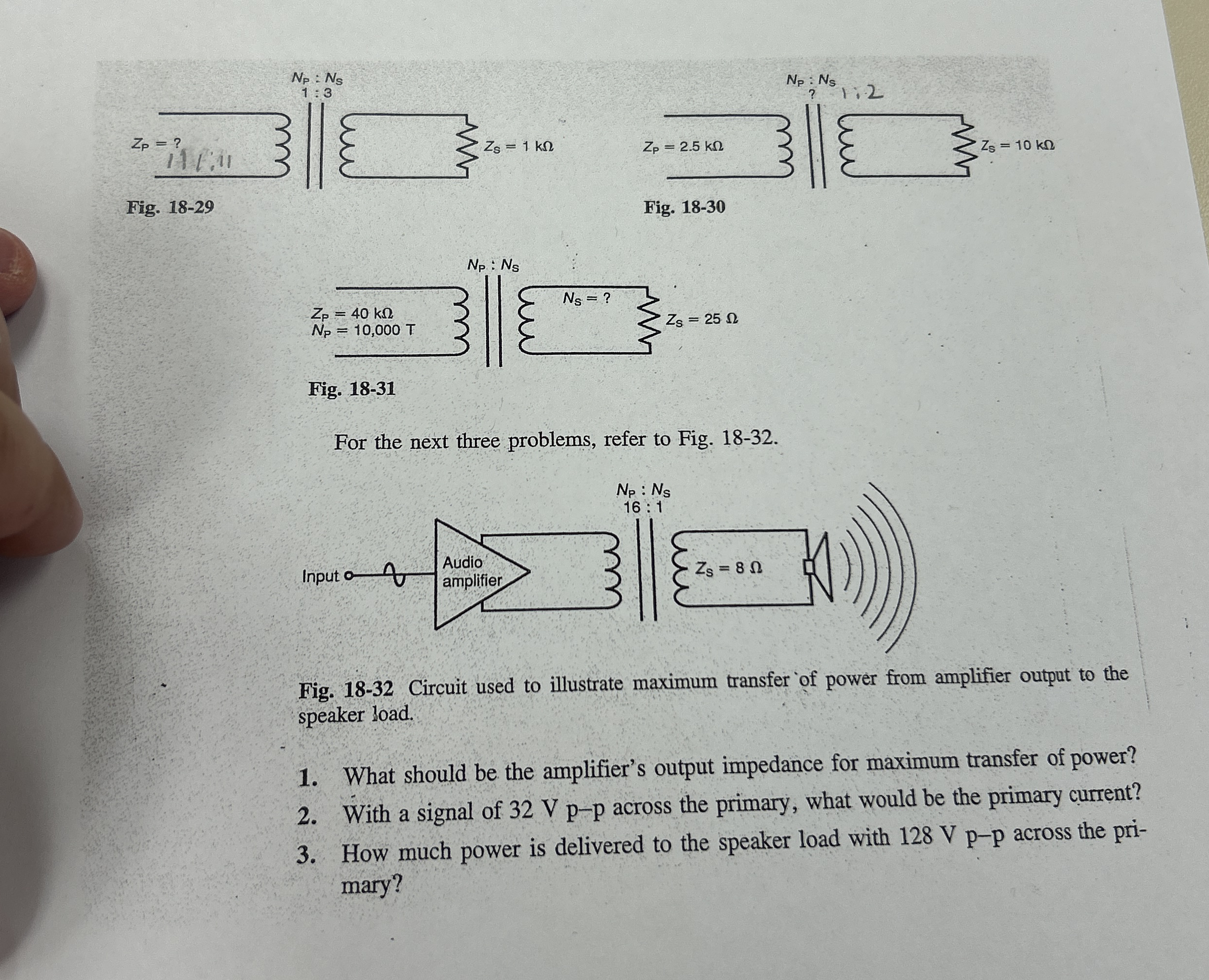
For the next three problems, refer to Fig.
Fig. Circuit used to illustrate maximum transfer of power from amplifier output to the speaker load.
What should be the amplifier's output impedance for maximum transfer of power?
With a signal of Vp p across the primary, what would be the primary current?
How much power is delivered to the speaker load with across the primary?
Step by Step Solution
There are 3 Steps involved in it
1 Expert Approved Answer
Step: 1 Unlock

Question Has Been Solved by an Expert!
Get step-by-step solutions from verified subject matter experts
Step: 2 Unlock
Step: 3 Unlock