

Question: Fig. 1 ( a ) shows the structural frame for a new building. One of the features is the use of mass timber frames. (
Fig. a shows the structural frame for a new building. One of the features is
the use of mass timber frames.
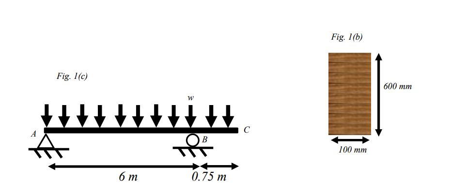
a If the glulam beams for these frames have the crosssection shown in Fig. b and are made from wood with a density of kgm determine the selfweight of the beam as a uniformly distributed load like that shown in Fig. c
b Now apply your load from a to the beam shown in Fig. c Determine the support reactions.
c You know whats next: sketch the shear force and bending moment diagram for the beam. Be sure to indicate the sign conventions. Also determine the location of zero shear and locations of zero moment.
d What forces do the columns in the frame need to resist from the weight of each glulam beam?
e Determine the location along the length of the beam and magnitude of the maximum compression and tensile normal stress on the top of the beam, and on the bottom of the beam.
f Compare these stresses to the typical bending strengths of Grade fE Douglas Fir glulam: MPa for
positive bending moment, and MPa for negative bending moment. Comment on the safety of these bFig. beam under their selfweight
Step by Step Solution
There are 3 Steps involved in it
1 Expert Approved Answer
Step: 1 Unlock

Question Has Been Solved by an Expert!
Get step-by-step solutions from verified subject matter experts
Step: 2 Unlock
Step: 3 Unlock