

Question: Fig. 2 ( a ) ( b ) JMJ 2 Fig. 2 ( a ) shows a simple portal frame. Normally the supports at the
Fig.
a
b
JMJ
Fig. a shows a simple portal frame. Normally the supports at the base of each column are pins, however to keep the analysis statically determinate, we make the support at a roller:
a Calculate the supports reactions.
Show the TAs your solution for the reactions before the end of the tutorial to receive your participation mark!
b Draw the axial force, shear force, and bending moment diagram for the frame in Fig. a
c Now consider the frame in Fig. b Without carrying out additional calculations, how will the axial force, shear force, and bending moment diagrams change as compared to Part a
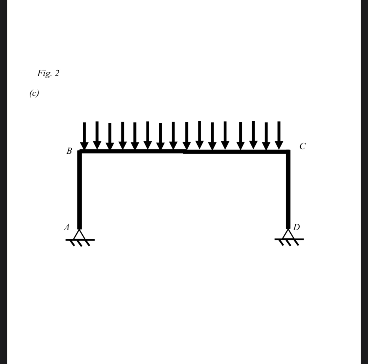
d Consider the frame in Fig. c Without carrying out calculations, sketch the approximate support reactions, axial force, shear force and bending moment diagrams. Compare and comment on the overall trends as compared to the frame in Part a Do you think there is any structural advantage to having pinpin supports vs pinroller supports for a portal frame?Fig.
a
b
JMJ
Fig.
c
Step by Step Solution
There are 3 Steps involved in it
1 Expert Approved Answer
Step: 1 Unlock

Question Has Been Solved by an Expert!
Get step-by-step solutions from verified subject matter experts
Step: 2 Unlock
Step: 3 Unlock