

Question: Fig. 2 For a given profile shown in Fig.Q 2 , design the u s and d s protection work. If seepage pressure distribution (
Fig.
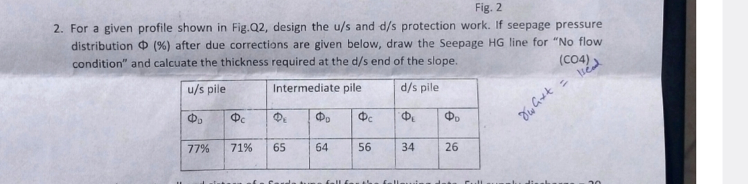
For a given profile shown in Fig.Q design the and protection work. If seepage pressure
distribution after due corrections are given below, draw the Seepage HG line for No flow
condition" and calcuate the thickness required at the end of the slope.
Step by Step Solution
There are 3 Steps involved in it
1 Expert Approved Answer
Step: 1 Unlock

Question Has Been Solved by an Expert!
Get step-by-step solutions from verified subject matter experts
Step: 2 Unlock
Step: 3 Unlock