

Question: Fig. P 3 . 1 2 Drilling mud circulation system. Fig. P 3 . 1 2 illustrates the mud - circulation system on an oil
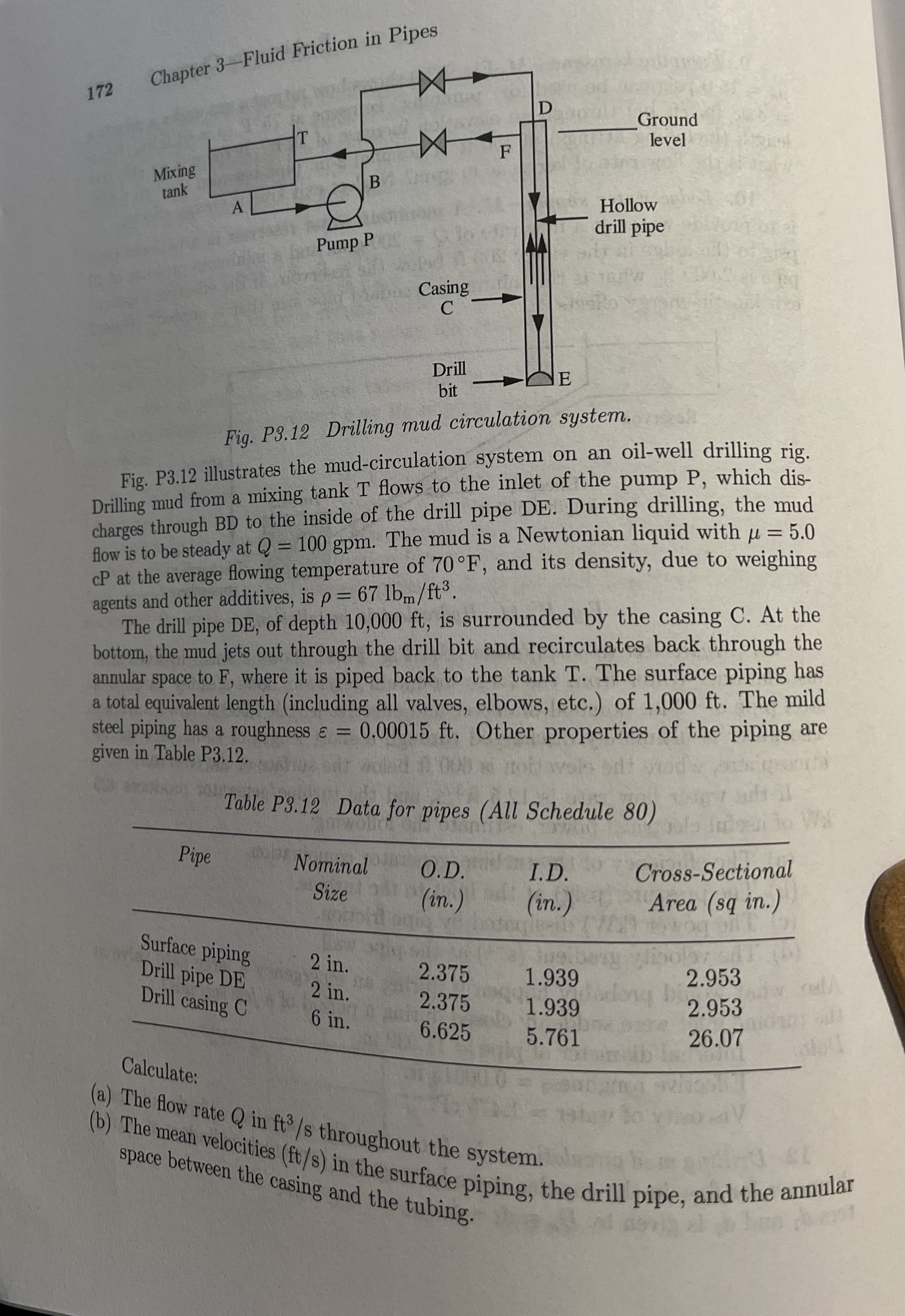
Fig. P Drilling mud circulation system.
Fig. P illustrates the mudcirculation system on an oilwell drilling rig.
Drilling mud from a mixing tank T flows to the inlet of the pump P which dis
charges through BD to the inside of the drill pipe DE During drilling, the mud
flow is to be steady at The mud is a Newtonian liquid with
cP at the average flowing temperature of and its density, due to weighing
agents and other additives, is
The drill pipe DE of depth is surrounded by the casing C At the
bottom, the mud jets out through the drill bit and recirculates back through the
annular space to where it is piped back to the tank T The surface piping has
a total equivalent length including all valves, elbows, etc. of The mild
steel piping has a roughness Other properties of the piping are
given in Table P
Calculate:
a The flow rate in throughout the system.
b The mean velocities in the surface piping, the drill pipe, and the annular
space between the casing and the tubing.
Step by Step Solution
There are 3 Steps involved in it
1 Expert Approved Answer
Step: 1 Unlock

Question Has Been Solved by an Expert!
Get step-by-step solutions from verified subject matter experts
Step: 2 Unlock
Step: 3 Unlock