

Question: Figure 1. Antenna azimuth position control system (a) layout and (b) schematic. Objective: Your objective will be to evaluate the system following specific tasks
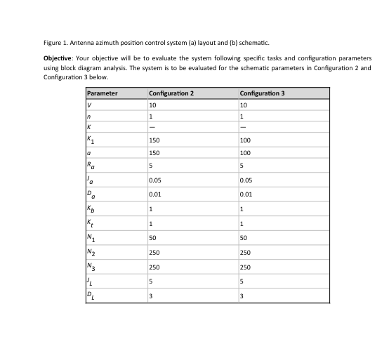
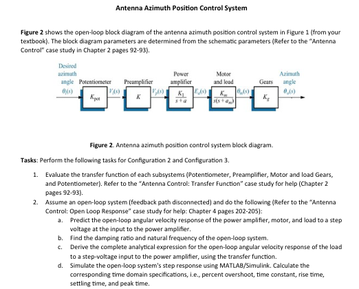
Figure 1. Antenna azimuth position control system (a) layout and (b) schematic. Objective: Your objective will be to evaluate the system following specific tasks and configuration parameters using block diagram analysis. The system is to be evaluated for the schematic parameters in Configuration 2 and Configuration 3 below. Parameter V n K Configuration 2 Configuration 3 10 10 1 1 K 150 100 a 150 100 Ra 5 5 0.05 0.05 D 0.01 0.01 0 Kb 1 1 Kt 1 1 N1 50 50 N 250 250 3 250 250 5 5 PL 3 3 Antenna Azimuth Position Control System Figure 2 shows the open-loop block diagram of the antenna azimuth position control system in Figure 1 (from your textbook). The block diagram parameters are determined from the schematic parameters (Refer to the "Antenna Control" case study in Chapter 2 pages 92-93). Desired azimuth angle Potentiometer Preamplifier Power amplifier Motor and load Azimuth Gears angle 0(5) VAS) K Eds) K (1) 05) Kj Figure 2. Antenna azimuth position control system block diagram. Tasks: Perform the following tasks for Configuration 2 and Configuration 3. 1. Evaluate the transfer function of each subsystems (Potentiometer, Preamplifier, Motor and load Gears, and Potentiometer). Refer to the "Antenna Control: Transfer Function" case study for help (Chapter 2 pages 92-93). 2. Assume an open-loop system (feedback path disconnected) and do the following (Refer to the "Antenna Control: Open Loop Response" case study for help: Chapter 4 pages 202-205): a. Predict the open-loop angular velocity response of the power amplifier, motor, and load to a step voltage at the input to the power amplifier. b. Find the damping ratio and natural frequency of the open-loop system. c. Derive the complete analytical expression for the open-loop angular velocity response of the load to a step-voltage input to the power amplifier, using the transfer function. d. Simulate the open-loop system's step response using MATLAB/Simulink. Calculate the corresponding time domain specifications, i.e., percent overshoot, time constant, rise time, settling time, and peak time.
Step by Step Solution
There are 3 Steps involved in it

Get step-by-step solutions from verified subject matter experts