

Question: Figure 1 b A turning machine is set on the middle of a simply supported beam A B , as shown in Figure la .
Figure b A turning machine is set on the middle of a simply supported beam as shown in
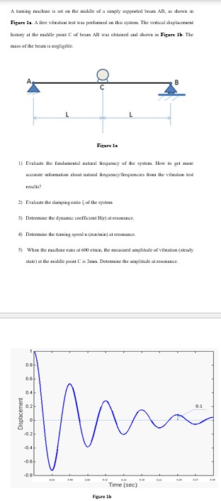
Figure la A free vibration test was performed on this system. The vertical displacement
history at the middle point C of beam AB was obtained and ghown in Figure The
mass of the beam is negligible.
Figure la
Evaluate the findamental natural frequency of the system. How to get more
accurate information about natural frequencyfrequencies from the vibration test
results?
Evaluate the damping ratio of the system
Determine the dynamic coefficient at resonance.
Determine the turning speed at resonance.
When the machine runs at the measured amplitude of vibration steacly
gtate at the middle point is mm Determine the amplitude at resonance.
A erming machine is set on the maldle of a simply supportal beats AB at shown in
Figare a A frec vieration lest was performed oe this syatern. The vertical displacement
leislory at the midill poine C of beam AB was obtaited and shown in Figure Ib The
mass of the beam is tegligible.
Evaluate the fixdamental natial frequency of the syokem. How to get etore
acturate information about matural froquencylfriquercies from the vibration test
result?
Evaluale the damping ratio of the systert
Detitmine the dyramic cocfficient at vesteanse.
Detitrine the eurning speod n nunimin al resatanct.
When the machire rans at rimin, the metiburad amplitule of vibration sieady
shatl at the radale poit C is rm Delernine the ampliade at etsonance.
Figure ib
Step by Step Solution
There are 3 Steps involved in it
1 Expert Approved Answer
Step: 1 Unlock

Question Has Been Solved by an Expert!
Get step-by-step solutions from verified subject matter experts
Step: 2 Unlock
Step: 3 Unlock