

Question: Figure 1 below shows a structure that is to be used as a storage facility in Durban, South Africa. The altitude in the area is
Figure below shows a structure that is to be used as a storage facility in Durban, South Africa. The altitude in the area is m above mean sea level and the surrounding areas consists of regular cover of vegetation and isolated obstacles with separations of up to obstacle heights. There are no noticeable features influencing the wind speed in the area and the mean design return period for the structure is years.Question marks
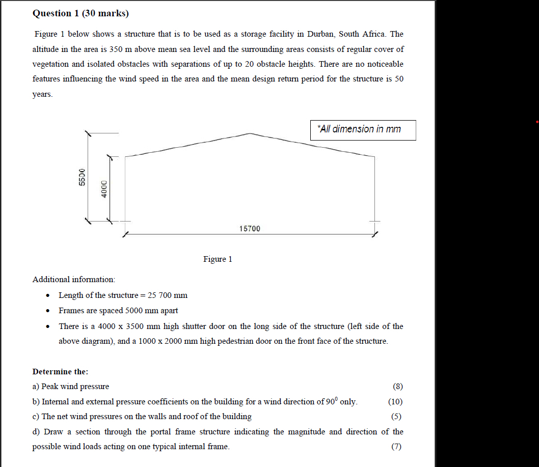
Figure below shows a structure that is to be used as a storage facility in Durban, South Africa. The
altitude in the area is above mean sea level and the surrounding areas consists of regular cover of
vegetation and isolated obstacles with separations of up to obstacle heights. There are no noticeable
features influencing the wind speed in the area and the mean design return period for the structure is
years.
Figure
Additional information:
Length of the structure
Frames are spaced apart
There is a high shutter door on the long side of the structure left side of the
above diagram and a high pedestrian door on the front face of the structure.
Determine the:
a Peak wind pressure
b Internal and external pressure coefficients on the building for a wind direction of only.
c The net wind pressures on the walls and roof of the building
d Draw a section through the portal frame structure indicating the magnitude and direction of the
possible wind loads acting on one typical internal frame.
Figure
Additional information:
Length of the structure mm
Frames are spaced mm apart
There is a x mm high shutter door on the long side of the structure left side of the above diagram and a x mm high pedestrian door on the front face of the structure.
Determine the:
a Peak wind pressure
b Internal and external pressure coefficients on the building for a wind direction of only.
c The net wind pressures on the walls and roof of the building
d Draw a section through the portal frame structure indicating the magnitude and direction of the possible wind loads acting on one typical internal frame.
Step by Step Solution
There are 3 Steps involved in it
1 Expert Approved Answer
Step: 1 Unlock

Question Has Been Solved by an Expert!
Get step-by-step solutions from verified subject matter experts
Step: 2 Unlock
Step: 3 Unlock