

Figure 1 shows a sketch of water distribution from a balancing tank to a service tank. The
Fantastic news! We've Found the answer you've been seeking!
Question:
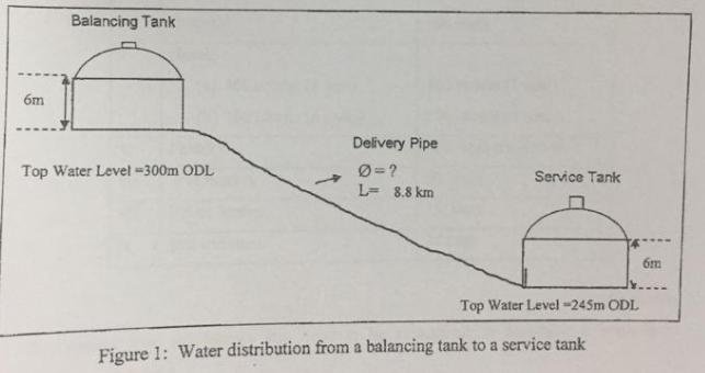
Figure 1 shows a sketch of water distribution from a balancing tank to a service tank. The flow rate is 4650 m 3 /day and the length of pipe connecting the two tanks is 8.8 km. Assume that head loss along the pipe as 2% and the proposed pipe material is new riveted steel. Other details of the two tanks are shown in Figure 1. Determine the appropriate size of the delivery pipe required from the balancing tank to the service tank.
Expert Answer:

Related Book For 

Finite Mathematics and Its Applications
ISBN: 978-0134768632
12th edition
Authors: Larry J. Goldstein, David I. Schneider, Martha J. Siegel, Steven Hair
Posted Date:
