

Question: Figure 1 Using the method of sections, determine the force in members BE and CE for the loaded truss shown in Figure 1 . Indicate
Figure
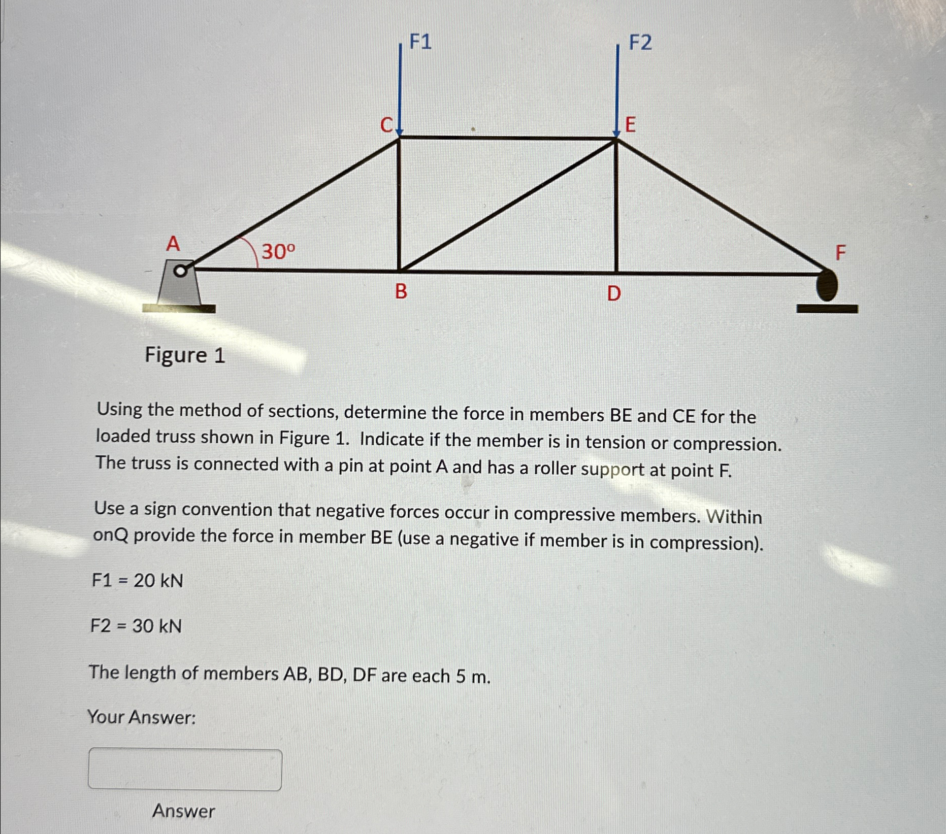
Using the method of sections, determine the force in members BE and CE for the loaded truss shown in Figure Indicate if the member is in tension or compression. The truss is connected with a pin at point A and has a roller support at point
Use a sign convention that negative forces occur in compressive members. Within on provide the force in member use a negative if member is in compression
The length of members AB BD DF are each
Your Answer:
Answer
Step by Step Solution
There are 3 Steps involved in it
1 Expert Approved Answer
Step: 1 Unlock

Question Has Been Solved by an Expert!
Get step-by-step solutions from verified subject matter experts
Step: 2 Unlock
Step: 3 Unlock