

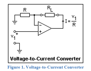
Question: Figure 1 . Voltage - to - Current Converter Q 1 . Consider the voltage to current converter circuit in Fig. 1 . a )
Figure VoltagetoCurrent Converter Q Consider the voltage to current converter circuit in Fig.
a Find the output impedance of this VCCS using Thevenins theorem.
b Derive the equation for the load current I.
c Draw the Norton equivalent circuit of this current source.
d Determine R to pass Vt mA through the load resistor RL
e Simulate this circuit in PSpice with the R value you have found in part d Change the load resistance RLkk and observe the current through the load. Comment on the result. Provide the circuit schematic and simulation output.
VVdcVccVVccV & Use the op amp uAEVAL
f Discuss the disadvantages of the voltage to current converter circuit in Fig.
g Discuss the steps of PCB Printed Circuit Board design and manufacturing process, and provide your PCB layout for this circuit.
Step by Step Solution
There are 3 Steps involved in it
1 Expert Approved Answer
Step: 1 Unlock

Question Has Been Solved by an Expert!
Get step-by-step solutions from verified subject matter experts
Step: 2 Unlock
Step: 3 Unlock