

Question: Figure 2 3 4 . 1 5 0 table [ [ MOTORS UNUIMITED ] , [ AC INDUCTION MOTOR ] , [ mernaly Pretecied
Figure
tableMOTORS UNUIMITEDAC INDUCTION MOTORmernaly Pretecied hoTypatStvie KBERUL yAPulte BSTrueP Pis HOUSte TOHPM Stivice facton craes B AMPEVots DECGRESCRASE coe D HCuas
tableBedldazDEsignLGa angcootFR RPM F HP AMaric PHHV AA V Aly
tableIEC MOTOR COMPANYHOUPNG TOThermaly Ftutadod NODCOREES CRISE PPVFRCME UHz HP PHCODE DHOURS VoLTsAMPS
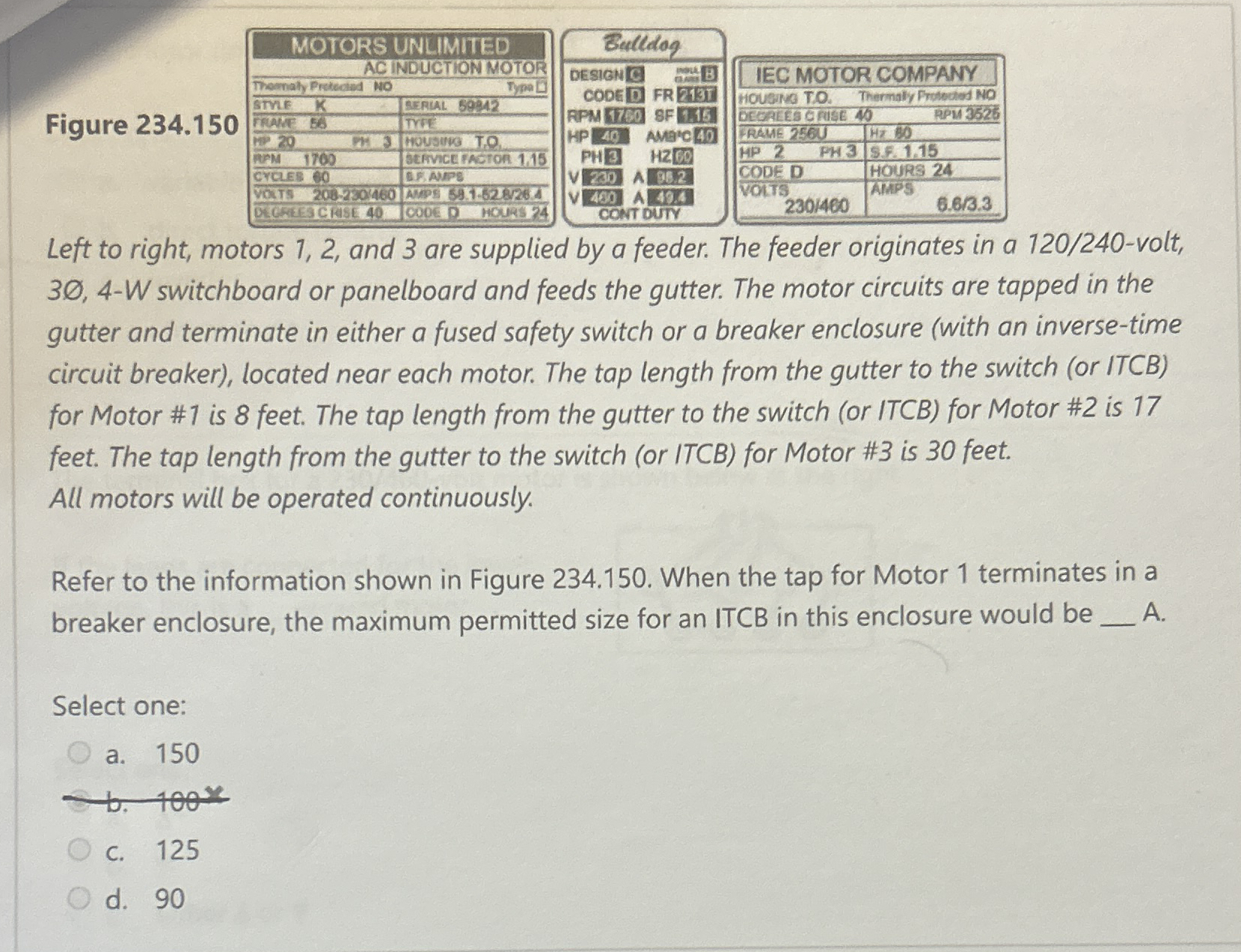
Left to right, motors and are supplied by a feeder. The feeder originates in a volt, W switchboard or panelboard and feeds the gutter. The motor circuits are tapped in the gutter and terminate in either a fused safety switch or a breaker enclosure with an inversetime circuit breaker located near each motor. The tap length from the gutter to the switch or ITCB for Motor # is feet. The tap length from the gutter to the switch or ITCB for Motor # is feet. The tap length from the gutter to the switch or ITCB for Motor # is feet. All motors will be operated continuously.
Refer to the information shown in Figure When the tap for Motor terminates in a breaker enclosure, the maximum permitted size for an ITCB in this enclosure would be A
Select one:
a
c
d
Step by Step Solution
There are 3 Steps involved in it
1 Expert Approved Answer
Step: 1 Unlock

Question Has Been Solved by an Expert!
Get step-by-step solutions from verified subject matter experts
Step: 2 Unlock
Step: 3 Unlock