

Question: Figure 2 illustrates a viscously damped two - degree - of - freedom system, used to model and analyze vibrations in mechanical structural systems. The
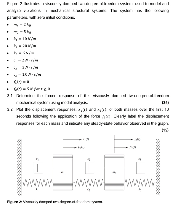
Figure illustrates a viscously damped twodegreeoffreedom system, used to model and analyze vibrations in mechanical structural systems. The system has the following parameters, with zero initial conditions:
for
Determine the forced response of this viscously damped twodegreeoffreedom mechanical system using modal analysis.
Plot the displacement responses, and of both masses over the first seconds following the application of the force Clearly label the displacement responses for each mass and indicate any steadystate behavior observed in the graph.
Figure : Viscously damped twodegreeoffreedom system.
Step by Step Solution
There are 3 Steps involved in it
1 Expert Approved Answer
Step: 1 Unlock

Question Has Been Solved by an Expert!
Get step-by-step solutions from verified subject matter experts
Step: 2 Unlock
Step: 3 Unlock