

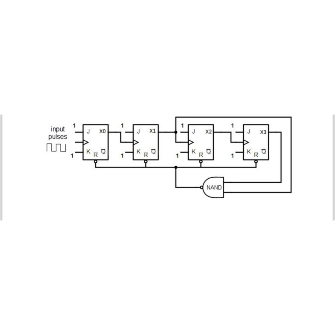
Question: Figure 2 shows a sequential logic circuit with four flip - flops ( XO , X 1 , X 2 and X 3 ) with
Figure shows a sequential logic circuit with four flipflops XO X X and X with externalclock input pulses applied to the clock input of the first flipflop. Use MMLogic to build the logiccircuit shown in Figure Save your design as BK where are the last digits of your matrix no
Step by Step Solution
There are 3 Steps involved in it
1 Expert Approved Answer
Step: 1 Unlock

Question Has Been Solved by an Expert!
Get step-by-step solutions from verified subject matter experts
Step: 2 Unlock
Step: 3 Unlock