

Question: Figure 2 : Simplified view of the isolation system between the safety spool and ceiling. Note that the mass of the spool and cabin are
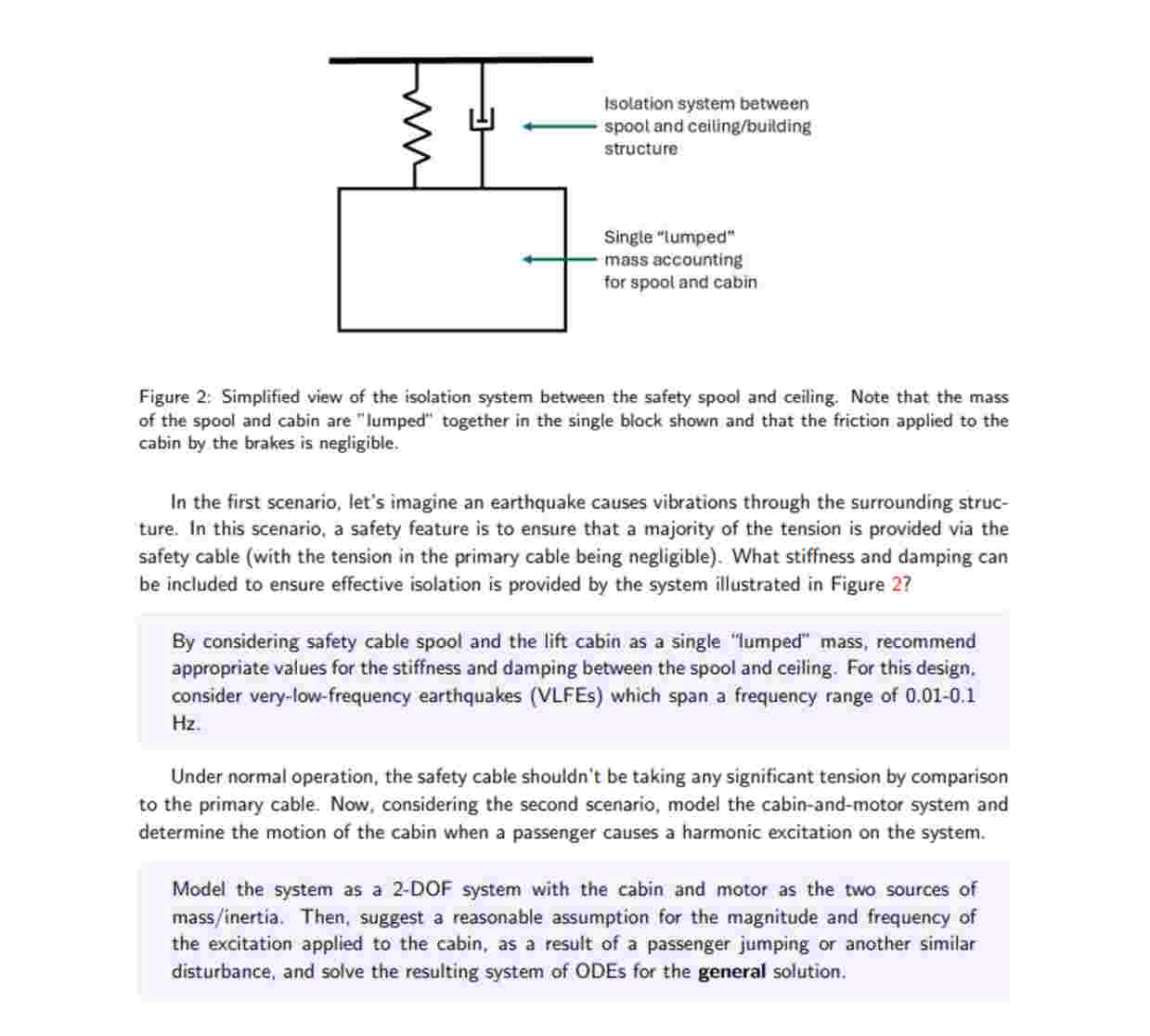
Figure : Simplified view of the isolation system between the safety spool and ceiling. Note that the mass of the spool and cabin are "lumped" together in the single block shown and that the friction applied to the cabin by the brakes is negligible.
In the first scenario, let's imagine an earthquake causes vibrations through the surrounding structure. In this scenario, a safety feature is to ensure that a majority of the tension is provided via the safety cable with the tension in the primary cable being negligible What stiffness and damping can be included to ensure effective isolation is provided by the system illustrated in Figure
By considering safety cable spool and the lift cabin as a single "lumped" mass, recommend appropriate values for the stiffness and damping between the spool and ceiling. For this design. consider verylowfrequency earthquakes VLFEs which span a frequency range of Hz
Under normal operation, the safety cable shouldn't be taking any significant tension by comparison to the primary cable. Now, considering the second scenario, model the cabinandmotor system and determine the motion of the cabin when a passenger causes a harmonic excitation on the system.
Model the system as a DOF system with the cabin and motor as the two sources of massinertia Then, suggest a reasonable assumption for the magnitude and frequency of the excitation applied to the cabin, as a result of a passenger jumping or another similar disturbance, and solve the resulting system of ODEs for the general solution. As part of our safety documentation, we have to account for what happens when one of our lifts fails. We've finished most of this, but there are a few more elements to this that we'd need to finalise the documentation. Specifically, we're considering one of our lifts with the following parameters.
begintabularlllll
Cabin mass & begintabularl
Safety spool
mass
endtabular & begintabularl
Primary cable
stiffness
endtabular & begintabularl
Cabin braking
coefficient
endtabular & begintabularl
Motor mass moment of
inertia
endtabular
hline kg & kg & mathrmkNmathrmm & mathrmkNsmathrmm & mathrmkgm
endtabular
Figure : Simplified lift model comprising a cabin, motor, safety spool, and associated cables.
Step by Step Solution
There are 3 Steps involved in it
1 Expert Approved Answer
Step: 1 Unlock

Question Has Been Solved by an Expert!
Get step-by-step solutions from verified subject matter experts
Step: 2 Unlock
Step: 3 Unlock