

Question: Figure 3: A single-position chest press machine (top) and diagram of alternative plate positions B, C, and D (bottom) Question 3: 50 points You nd
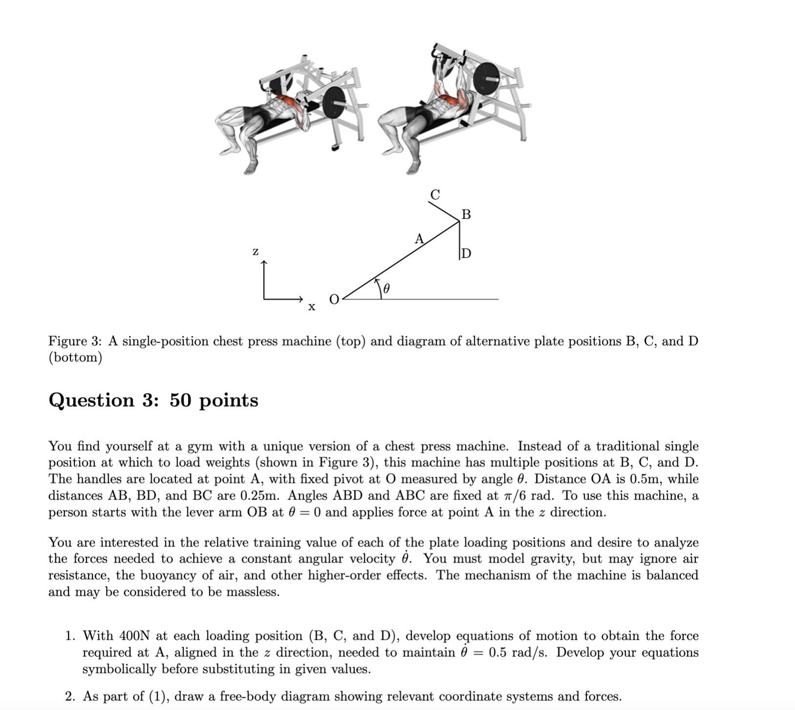
Figure 3: A single-position chest press machine (top) and diagram of alternative plate positions B, C, and D (bottom) Question 3: 50 points You nd yourself at a gym with a unique version of a chest press machine. Instead of a traditional single position at which to load weights (shown in Figure 3), this machine has multiple positions at B, C, and D. The handles are located at point A, with xed pivot at 0 measured by angle 0. Distance 0A is 0.5m, while distances AB, BD, and BC are 0.25m. Angles ABD and ABC are xed at 1r/6 rad. To use this machine, a person starts with the lever arm GB at 0 = 0 and applies force at point A in the z direction. You are interested in the relative training value of each of the plate loading positions and desire to analyze the forces needed to achieve a constant angular velocity 9. You must model gravity, but may ignore air resistance, the buoyancy of air, and other higher-order effects. The mechanism of the machine is balanced and may be considered to be massless. 1. With 400N at each loading position (B, C, and D), develop equations of motion to obtain the force required at A, aligned in the z direction, needed to maintain 0 = 0.5 rad/s. Develop your equations symbolically before substituting in given values. 2. As part of (1), draw a free-body diagram showing relevant coordinate systems and forces
Step by Step Solution
There are 3 Steps involved in it

Get step-by-step solutions from verified subject matter experts