

Question: Figure 3 shows a process for the reaction between Feod A and Feed B to produce Product C according to the reaction: A+BC+LightByproducts Whilst the
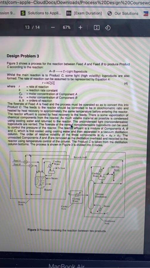
Figure 3 shows a process for the reaction between Feod A and Feed B to produce Product C according to the reaction: A+BC+LightByproducts Whilst the main reaction is to Product C, some light (high volatility) byproducts are also formed. The rate of reaction can be assumed to be represented by Equation 4 : r=kCA4Ciwherer=rateofreactionk=reactionrateconstantCA=molarconcentrationofComponentACB=molarconcentrationofComponentBa,b=ordersofreaction The flowrate of Feed A is fixed and the process must be operated so as to convert this into Product C. The feeds to the reactor should be controlled to be in stoichiometric ratio and heated by heat recovery to approximalely the same temperature belore entering the reactor. The reactor effluent is cooled by heat recovery to the feeds. There is some vaporization of chemical components from the reactor. As much volatile material as possible is condensed using cooling water and returned to the reactor. The uncondensed light (noncondensable) byproducts are vented. The flowrate of the vented noncondensable byproducts can be used to control the pressure of the reactor. The react r eflluent is a mixture of Components A,B and C, which is first cooled using cooling water and then separated in a vacuum distillation column. The order of relative volatility of the three components is a an>as>a0. The unreacted Components A and B are removed as the distillation overhead and recycled to the reactor using temperature control of the column. The Product C is taken from the distillation column bottoms. The process is shown in Figure 3 is divided into 3 nodes. Figure 3 Process involving the reaction between two products. a) Develop a conceptual design for the control system for the reactor node in Figure 3 assuming the reactor operates in isolation. The reactor temperature and pressure both need to be controlled. Give a short description to justify the basis of the conceptual design. [13 Marks] b) Develop a conceptual design for the reactor effluent cooler node control system in Figure 3 assuming the cooler operates in isolation. The cooling water should be used to control the temperature to be fed to the distillation. [3 Marks] c) Develop a conceptual design for the vacuum distillation node control system in Figure 3 assuming the distillation operates in isolation. Give a short description to justify the basis of the conceptual design. [13 Marks] d) Combine the node control systems to form an overall process control system and identify any features in the control system that might ff problematic. [3 Marks] e) Suggest design changes to eliminate conllicts and ensure that the overall material balance can be controlled in a stable operation. Give a short description to justify the basis of the conceptual design. Figure 3 shows a process for the reaction between Feod A and Feed B to produce Product C according to the reaction: A+BC+LightByproducts Whilst the main reaction is to Product C, some light (high volatility) byproducts are also formed. The rate of reaction can be assumed to be represented by Equation 4 : r=kCA4Ciwherer=rateofreactionk=reactionrateconstantCA=molarconcentrationofComponentACB=molarconcentrationofComponentBa,b=ordersofreaction The flowrate of Feed A is fixed and the process must be operated so as to convert this into Product C. The feeds to the reactor should be controlled to be in stoichiometric ratio and heated by heat recovery to approximalely the same temperature belore entering the reactor. The reactor effluent is cooled by heat recovery to the feeds. There is some vaporization of chemical components from the reactor. As much volatile material as possible is condensed using cooling water and returned to the reactor. The uncondensed light (noncondensable) byproducts are vented. The flowrate of the vented noncondensable byproducts can be used to control the pressure of the reactor. The react r eflluent is a mixture of Components A,B and C, which is first cooled using cooling water and then separated in a vacuum distillation column. The order of relative volatility of the three components is a an>as>a0. The unreacted Components A and B are removed as the distillation overhead and recycled to the reactor using temperature control of the column. The Product C is taken from the distillation column bottoms. The process is shown in Figure 3 is divided into 3 nodes. Figure 3 Process involving the reaction between two products. a) Develop a conceptual design for the control system for the reactor node in Figure 3 assuming the reactor operates in isolation. The reactor temperature and pressure both need to be controlled. Give a short description to justify the basis of the conceptual design. [13 Marks] b) Develop a conceptual design for the reactor effluent cooler node control system in Figure 3 assuming the cooler operates in isolation. The cooling water should be used to control the temperature to be fed to the distillation. [3 Marks] c) Develop a conceptual design for the vacuum distillation node control system in Figure 3 assuming the distillation operates in isolation. Give a short description to justify the basis of the conceptual design. [13 Marks] d) Combine the node control systems to form an overall process control system and identify any features in the control system that might ff problematic. [3 Marks] e) Suggest design changes to eliminate conllicts and ensure that the overall material balance can be controlled in a stable operation. Give a short description to justify the basis of the conceptual design
Step by Step Solution
There are 3 Steps involved in it

Get step-by-step solutions from verified subject matter experts